Correct setting for triggering solid state relays

Battery protection unit with three relays EV200AAANA + Power Rectifier Diode Module MDK200-16 + resistor. The battery will consist of 4*K9 in high-voltage mode, working in conjunction with DEYE SUN-30K


first relay - overdischarge protection
second relay - overcharge protection
third relay - precharge

please help me choose the right one for each relay:

My system is growing :slight_smile:

I assembled the BMS in a case and while in test mode I supplied power from an external power supply - everything works :slight_smile:

I need help from the community. Please help me set the correct conditions for the operation of the NO relay.

Conditions for closing relay #1: no obstacles to charging
Conditions for closing relay #2: no obstacles to discharging
Conditions for closing relay #3: starts first, only after the first turn on of the system and only for the time of starting relays 1 and 2
after starting relay 1 and relay 2, relay 3 is turned off

Is there a tool that allows you to invert the relay state for parameters

  1. CmuAlert Low Vlot - when value = true, relay action is off
  2. CmuAlert Hi Vlot - when value = true, relay action is off

Where does this battery protection unit come from? Disabling charge or discharge through relays does not seem to make any sense to me. What should be the purpose of that?
You’re running a Deye Sun 30k, which is a hybrid inverter. What could be the use case to open the relay for charging or discharging. Current flows through the battery can often switch direction. Imagine today is very cloudy, sunshine is only for a few minutes scattered around the day. Secondly your consumption is today pretty high. Now when sun comes out behind clouds, battery will be charging. And if the sun hides behind clouds, battery will be discharged. If now one of the relays (charging, discharging) is open, you hybrid inverter will constantly run into error states.
So, please describe, why this battery protection unit provides some use case for you?

1 Like

the proposed protection side acts as a fuse against overcharging or overdischarging of the battery in the event that the inverter fails, does not turn off the current when the battery cells reach a critical state.
Using a diode bridge, we are able to implement a limitation of current movement in a specific direction (discharge / charge) according to the state of variables (CmuAlert Low Vlot / CmuAlert Hi Vlot)
while the direction for current movement in which there are no problems remains operational and will allow the equipment to exit emergency mode without operator intervention.
Also, I would like to turn off / on the relay through the precharge unit to reduce the electric arc inside the relay when triggered.

Other high-voltage BMS have such a scheme - I spied on it and did not invent it :frowning:

If you suddenly know how to invert the default states for the expansion board relay, I would be very grateful for your answer.

You need to implement two control layers:

  1. The BMS controls the inverter through data communication, prefered a CAN-Bus. Here the information about allowed charge and discharge currents needs to be communicated to the Deye hybrid inverter. This can also include to stop charge and discharge by communicating according charge or discharge currents as 0A, when battery is full or empty.
  2. A relay can only be the last option, if data communication and current limitation fails.

These relays can not switch high currents a lot of times. That can do that in emergency and should only do that in emergency situations.

And I am sure you will damage not only the relay but also the inverter if you cut charge or discharge currents a lot.

To sum this up: I would suggest to only use a single kilovac to cut the battery in emergency situations. And yes, I am also using a precharge unit. And how to control that is described here.

Some more explanations:
I use Victron Energy inverters. Discharging is stopped by the BMS through sending “discharge current limit” as 0A. Charging is stopped by having
a) a maximum charge voltage of 3.45V per cell (LFP) defined in the inverter
b) Batrium sends a dynamic charge voltage between 3.37V and 3.45V to the inverter (Dynamic Voltage Targets).
If battery is full and inverter tries to charge more, it can not due to configured maximum charge voltage. If battery is empty and inverter does not act on Batriums command, CriticalOK state will become false and single central kilovac will open.

2 Likes

I am very grateful to you for your participation and attention to my request for help! Everything you described is correct!!
All relays except precharge are not for regular use but as protection, in case of emergency - and I hope or even am sure that this event will never happen. Batrium communicating via CAN will tell the inverter how and when to work and this is 100% enough.
But I want to implement such a protection measure as described, as you once wanted to make yours, looking for a solution for 4 years.
Here I understand - that I have not yet lost hope for James’s answer on how to invert the default relay states and make precharge for any transition of relay states standard.

Even if after implementation these relays will work only twice: the first time at the first turn on and the second at the last turn off

Hello everyone, additional thoughts on the logical part of the circuit operation:


all 3 relays are normally open. iin case of controller failure, the battery will be disconnected from the inverter
To implement this scheme, the following modifications to the controller functionality are needed the ability to invert the default relay states.
And the maximum task :slight_smile: is: the ability to collect conditions in arrays. Example: (BattOk + CmuAlert Hi Volt = false), this will save the board’s relay outputs

Hi Dimitrii,

This is a very unconventional project, with a few caveats. I would like to inform you on how we usually do things before you decide on your final system layout

@kleini, You are correct in your understanding of our “severity” scale, thank you for sharing it with Dimitrii. In summary it is:

  1. Normal/Limited Charge/DIscharge limits - These are governed by your Control Logic settings, and sent to the inverter to stay within.
  2. Charge/Discharge cutouts - if for some reason the inverter strays outside its limits, or thinks the pack voltage is different that what it is etc. then we will tell it to stop charging/discharging by setting the limits to zero. You will never reach these in normal operation
    Deye inverters like Dimitrii’s interpret 0 charge limit as “discharge heavily now”, so I advise Dimitrii to turning on the flag Remote Amp - Off = Non-Zero under Control > Charging > Extra Parameters to send 0.1A instead.
  3. Critical - This is if the inverter is not responding at all. If you are not prepared to run at your system with a fire axe, you should not be entering this state. It should throw a circuit breaker, and disconnect your battery completely.

@Dimitrii, We would typically rely on CAN control (like your inverter is equipped with) to manage the flow of current. Contactors are only for no-load scenarios. In an EV battery pack (their typical origin), they are only used for preventing parasitic load from draining the pack when not in use, and isolating it during service. They may not have the ability to stop a 20kA short (like an MCCB can), and tend to fuse shut after a few actuations under load. For reference most EVs use Pyrofuses that explode to extinguish an arc under load.

If you were starting from scratch I would suggest an MCCB, but since you have invested significant effort already, you can still do your proposed solution, but you will need to enable a few options:

  • Since you do not have a critical safety device, both your contactors should open in a critical scenario. This can be achieved by enabling Pause When Critical Off in Control > Charging AND Discharging > Extra Parameters.
  • You should set your Charge and Discharge rules to reflect the conditions you want to prevent, and use charge and discharge rather than high cell voltage for example, to trigger your contactors. This gives you the ability to trigger them based on temperature, SoC, cell voltage, shunt voltage, not just one of those. Then set your Hardware > Expansion outputs to Charging On/Limited and Discharging On/Limited
  • You will also need to set two options under Control > Critical > Extra Parameters:
    • Skip Startup Preload ON - This does a full check before turning on relay outputs etc
    • Stop Charge/Dischg Prior - This will attempt to stop current over CAN before disconnecting contactors to try and protect your contactors

Please let me know if you have any questions about the above, as your system is quite non-standard for a home storage project

1 Like

Thanks for the reply James. Your controller is awesome and I’m glad I found you to help me with my project!!

I have a few additional points that I would like to clarify:

  • the edits you made to the controller settings have been made - thank you:

  • Remote Amp - Off = Non-Zero “Charging AND Discharging”

  • Pause When Critical Off “Charging AND Discharging”

  • Skip Startup Preload ON

  • Stop Charge/Dischg Prior

  • the system uses MCCB “TOMZN TOB1Z-125 C125 2P DC 1000V 125A” and also purchased MCCB “TOMZN TOM7Z-125/2300 DC-MCCB: DC1000V 2P 125A” but its dimensions are not convenient :frowning: and for now I decided to install a more compact version.

  • the option you suggested with control of protective relays via the parameters
    Charging On/Limited or Discharging On/Limited looks good, but I can’t think of a scenario where it’s physically worth disconnecting the battery from the inverter except for one emergency - overcharging or overdischarging one of the cells. All other parameters: temperature, soc, current overload… let them be controlled via CAN and work in normal mode, there is a controller for this and it works in conjunction with the inverter via CAN.
    I want the relays to start (open) when the thresholds set by default for the selected battery type (lifepo4 long life) are exceeded, namely lo Cell Volt 2.5, hi Cell volt 3.75. I consider all other situations to be normal and I don’t plan to disconnect the battery from the inverter.

  • I also want to keep the percharge option that was implemented in the @Kuchengeschmack thread, everything will work out there.

P.S. If you can’t find a method to invert the relay status (from NO to NC), here’s how I see the implementation of the selected option:


Good day, I am looking at the parameters and it seems I haven’t figured out all the capabilities of the controller. James, please help me!! Let’s go through an example to understand the algorithm of the controller and its capabilities.

Here is an example of the control actions after the BMS (Battery Management System) is turned on:
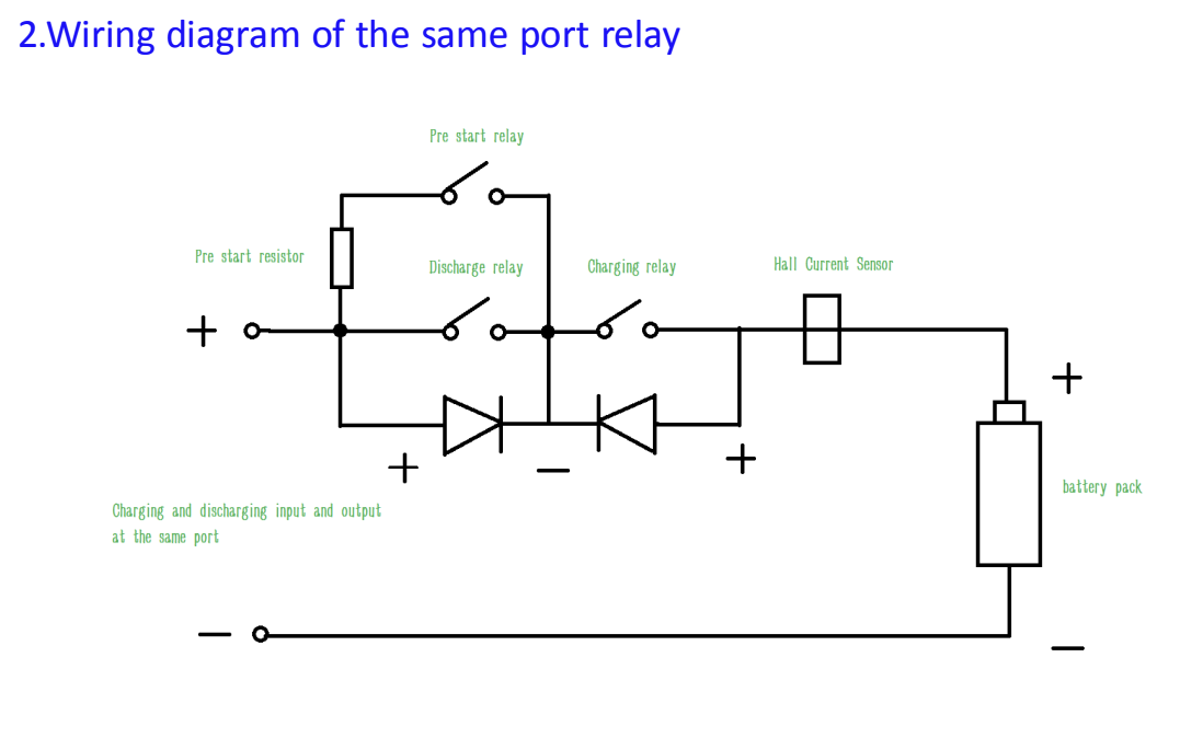
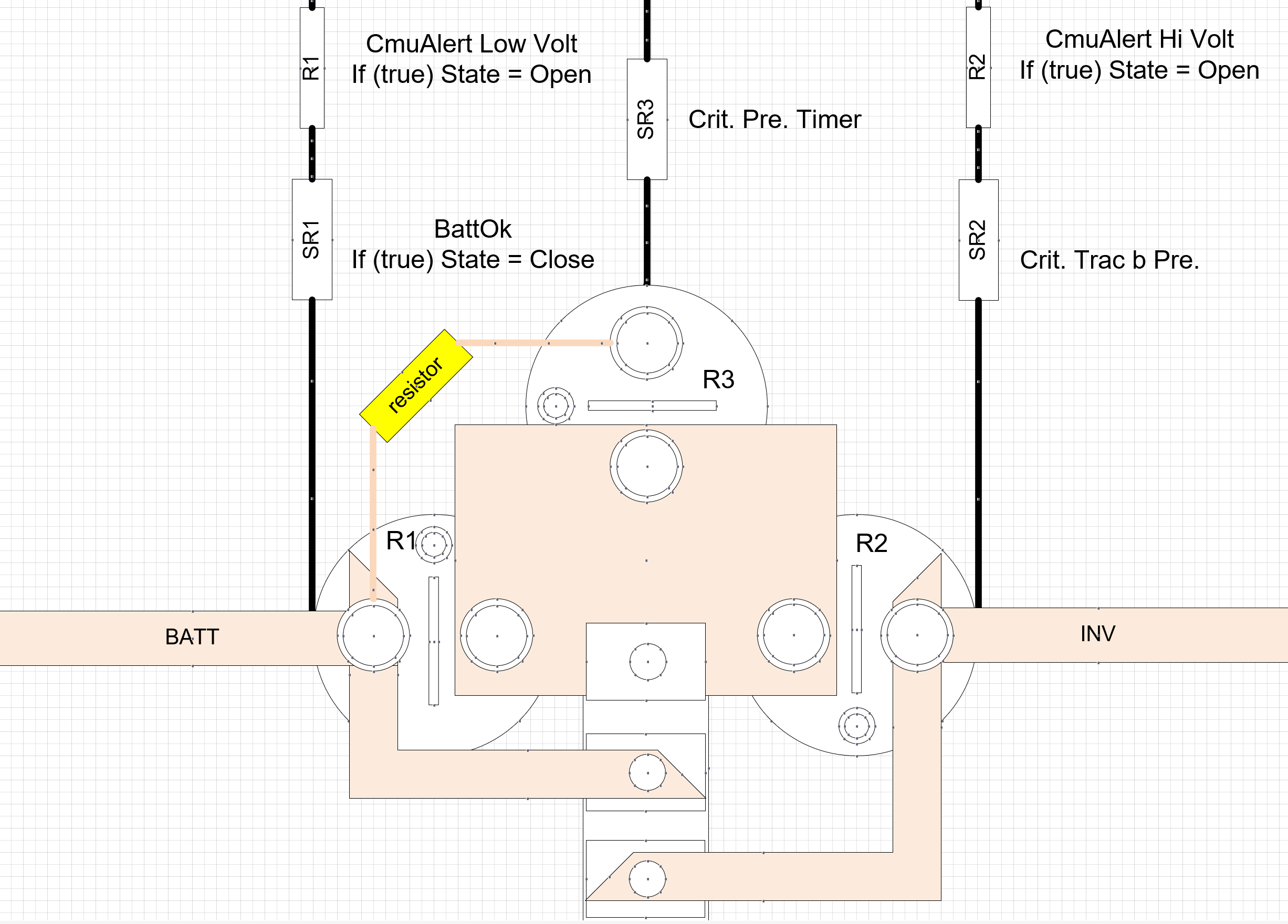
Precharge Stage

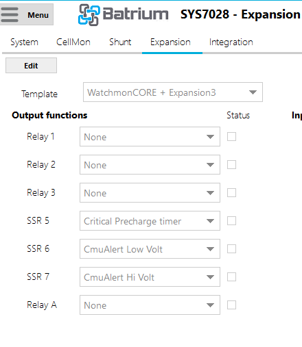
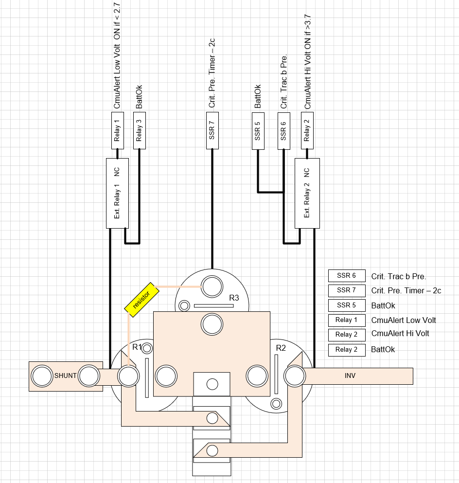
SSR6 = ON to start the precharge process, “allowing battery charging”;
SSR7 = ON for a duration of (Precharge Time 2s) “allowing battery discharge through the resistor”;
SSR5 = ON while the time hasn’t expired - 2s for precharge;
SSR7 = OFF upon timer expiration of 2s. Precharge stage completed;

Normal Operation Mode of BMS

SSR6 = ON - allowing battery charging;
SSR5 = ON - allowing battery discharge;
SSR7 = OFF;

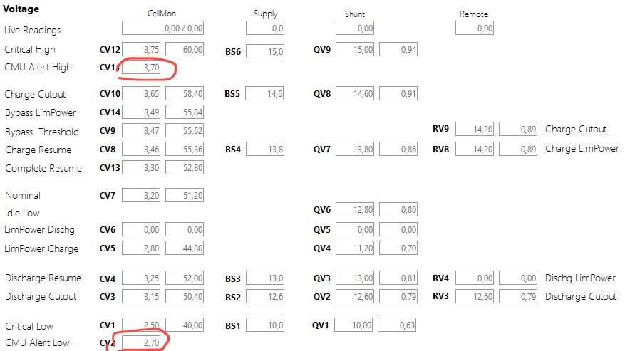
If the cell status value falls within the range: Critical->Hi Cell Volt = 3.75 and Charging->Cell Hi Cutout = 3.65v, the following relay actions occur:

SSR6 = OFF - prohibiting battery charging;
SSR5 = ON - allowing battery discharge;
SSR7 = OFF;

The transition from this mode to normal mode occurs by switching relay SSR6 = ON.

If the cell status value falls within the range: Critical->Low Cell Volt = 2.5 and Discharging->Cell Low Cutout = 3.15v, the following relay actions occur:

SSR6 = ON - allowing battery charging;
SSR5 = OFF - prohibiting battery discharge;
SSR7 = OFF;

The transition from this mode to normal mode is carried out through the precharge procedure with the following actions:

SSR6 = ON - maintaining the previous state of allowing battery charging;
SSR7 = ON for a duration of (Precharge Time 2s) “allowing battery discharge through the resistor”;
SSR5 = ON while the time hasn’t expired - 2s for precharge;
SSR7 = OFF upon timer expiration of 2s;

If the variable BattOK = 0, the emergency shutdown procedure is initiated through Stop Charge/Discharge Prior:

  1. Set relay SSR7 to the closed state for precharge, duration (Precharge Time 2s);
  2. Open relay SSR5;
  3. Open relay SSR7;
  4. Open relay SSR6.

Without manual intervention, the battery will not return to normal mode.

tell me how to change the values ​​of the parameters CV11 to 3.7, CV2 to 2,75.
Presumably this will allow using the triggers CmuAlert Low Vlot and CmuAlert Hi Vlot as I want and this will happen before the BMS switches to emergency mode.

I changed the settings of the necessary parking meters :)) the controller is SUPER
help invert the default state of the relay and I will move on to the tests!!! :slight_smile:

Hi Dimitrii,

Any custom logic you want that is beyond standard should be done with your own hardware/software, yes.

Most of the main control conditions (charge allowed, discharge allowed, critical) have inverted options as those are the ones 99.9% of people use.

The precharge output will not do this, and isn’t intended to. It is meant for charging large capacitors in inverters / motor drives at a low current on system startup. Sending large inverter currents through the precharge resistor will probably cause it to heat and fail quickly.

Switch from LiFePO4 LongLife to Custom. You can then set them where you like.

I should mention though, since you are doing things in an unconventional way, you are responsible for how this turns out. If your inverter, battery, BMS or contactors are damaged due to this, that’s on you.

Thanks James, I revised the algorithm after your answer and here is the scheme that I will try to implement as the first beta :slight_smile:

I can’t find and I don’t know what happens to the relays that are controlled by the variables:

  • Crit. Pre. Timer
  • Crit. Trac b Pre.
    after the 2s timer has finished on precharge, but I believe that they remain in the open position.
    after the percharge and checking all the battery parameters, we will receive the BattOK status, and it will put the battery into operation with equalized potentials after the precharge

and only according to CMU alerts, we will lock the current flow in one of the two directions until the BattOK status changes to false and an emergency shutdown of everything that is occurs.