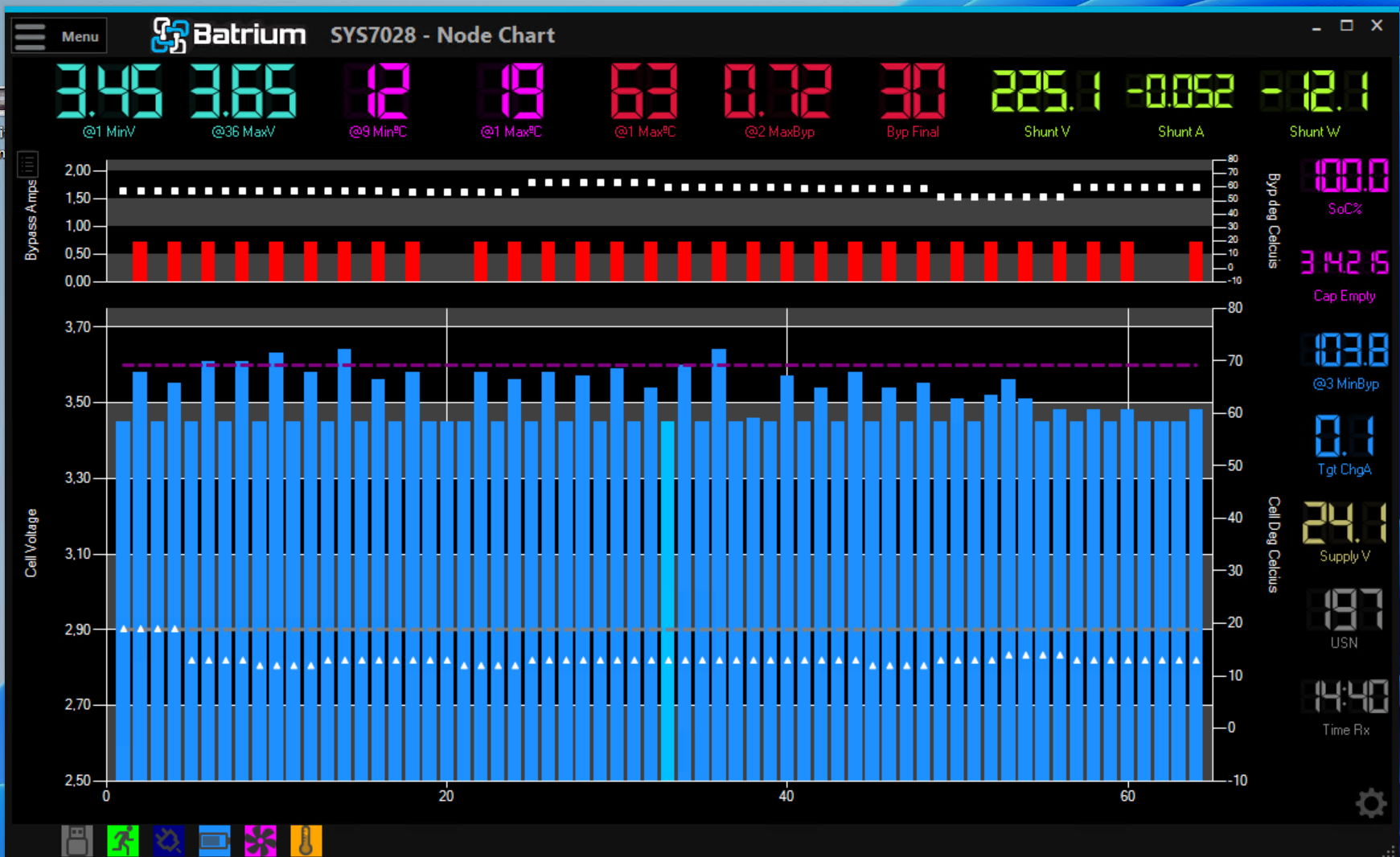
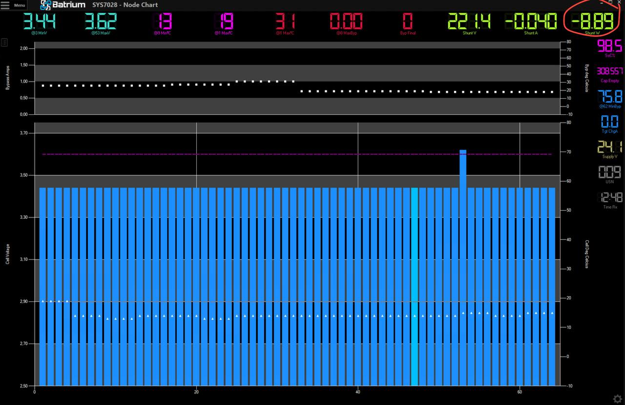
Tell me who knows why the bypass indicator is on in cell 54
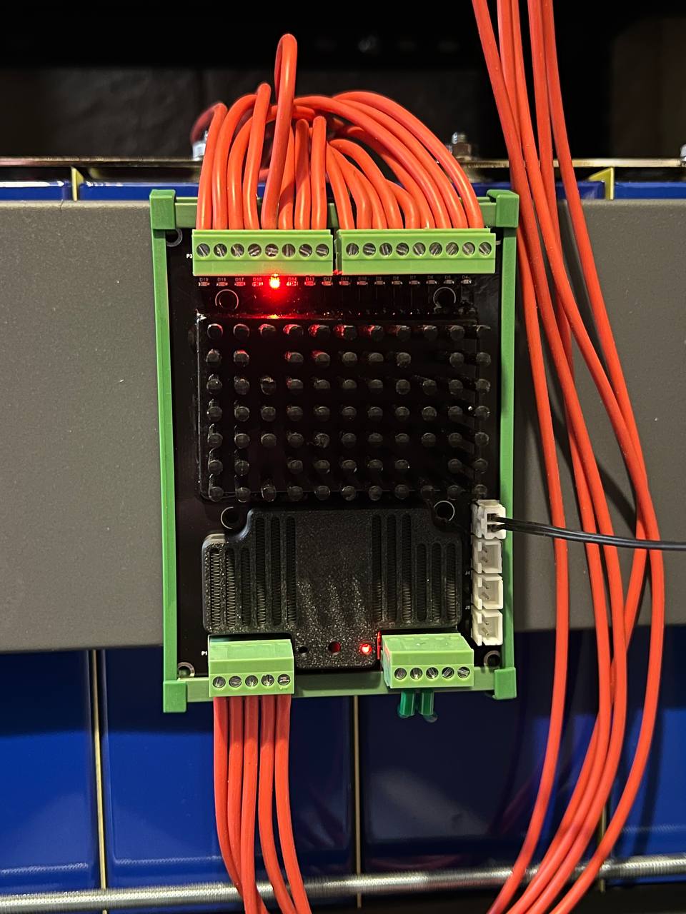
this cell is not particularly different from the others
Tell me who knows why the bypass indicator is on in cell 54
I have some points/questions for you ![]()
For your question with the cell 54 in bypass, I would recommend you to do the bypass tester sequence in the system settings.
Thanks for your informations ![]()
It is right, here your diodes are protecting the malfunction of the Deye. They are currently in contact with BYD and want to fix the issue, but your system has here an HW protection, which is great ![]()
Please be aware that you should only open charge/discharge relay if there is nearly no current flowing! But when the BMS detects under or overvoltage it immediately sends 0A as target current. So you should be fine with that.
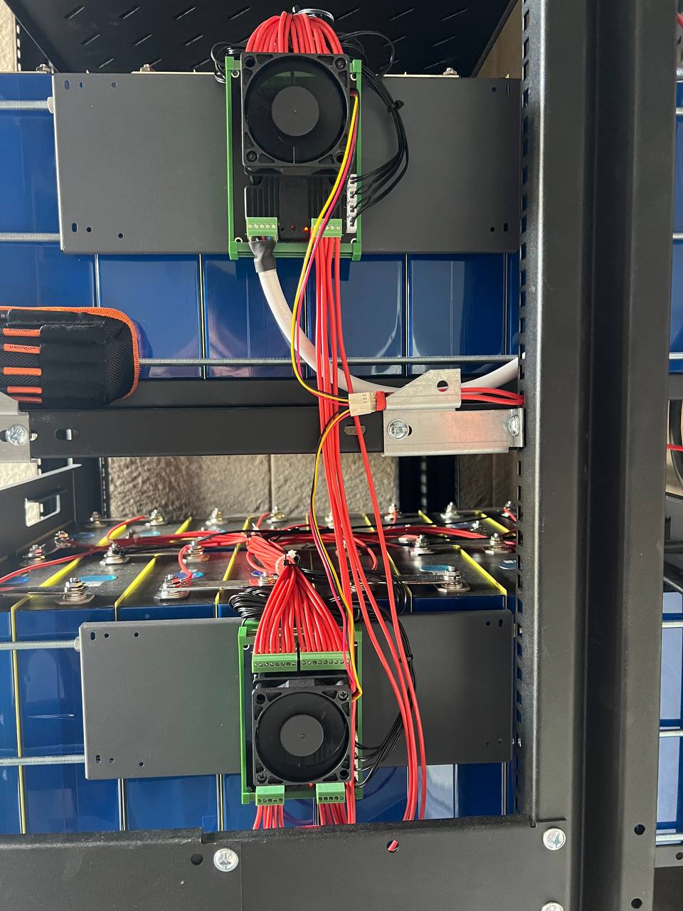
I also have active balancers mounted, but a better option is to mount the 60x60 fans, then you will be able to nearly balance 24/7; my active balancers have never been running up to now, because the passive balancing of Batrium K9 is really good with the mounted fans.
It is not yet clear why the low cell charge trigger is triggered when the upper cell threshold is reached ![]() but these are trifles - we will figure it out later
but these are trifles - we will figure it out later
I still suggest, this is not a good behavior of your inverter battery integration.
Way before it happens, what you describe in the picture, the charge current limit should be reported as 0A to the inverter through a CAN-Bus integration and the inverter should stop charging the batteries. This must be the first line of problem defense.
The second line of defense can then be to cut connections. But don’t use cut connections for everyday use. This will destroy your kilovacs over time and when you need them, they will not work anymore.
Thank you for your attention and engagement with my project. For me, this is a hobby, and even if I face failure, I won’t be too upset. The setup is in a standalone room, so even in the case of a fire, I’ll manage it. ![]()
I’ve now realized through experimentation that the state-of-charge triggers you suggested are better than the ones I’ve been using. I plan to switch to them after completing the balancing process. If you have suggestions that you might hesitate to test due to responsibility as a project participant, but you think they could improve the algorithm, please share them! Thank you again for showing interest in my topic.
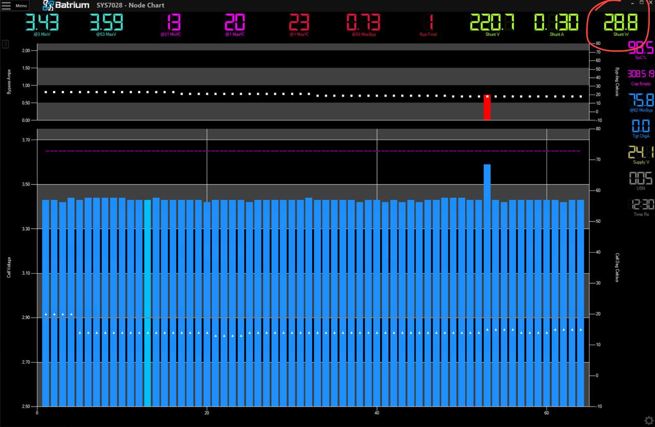
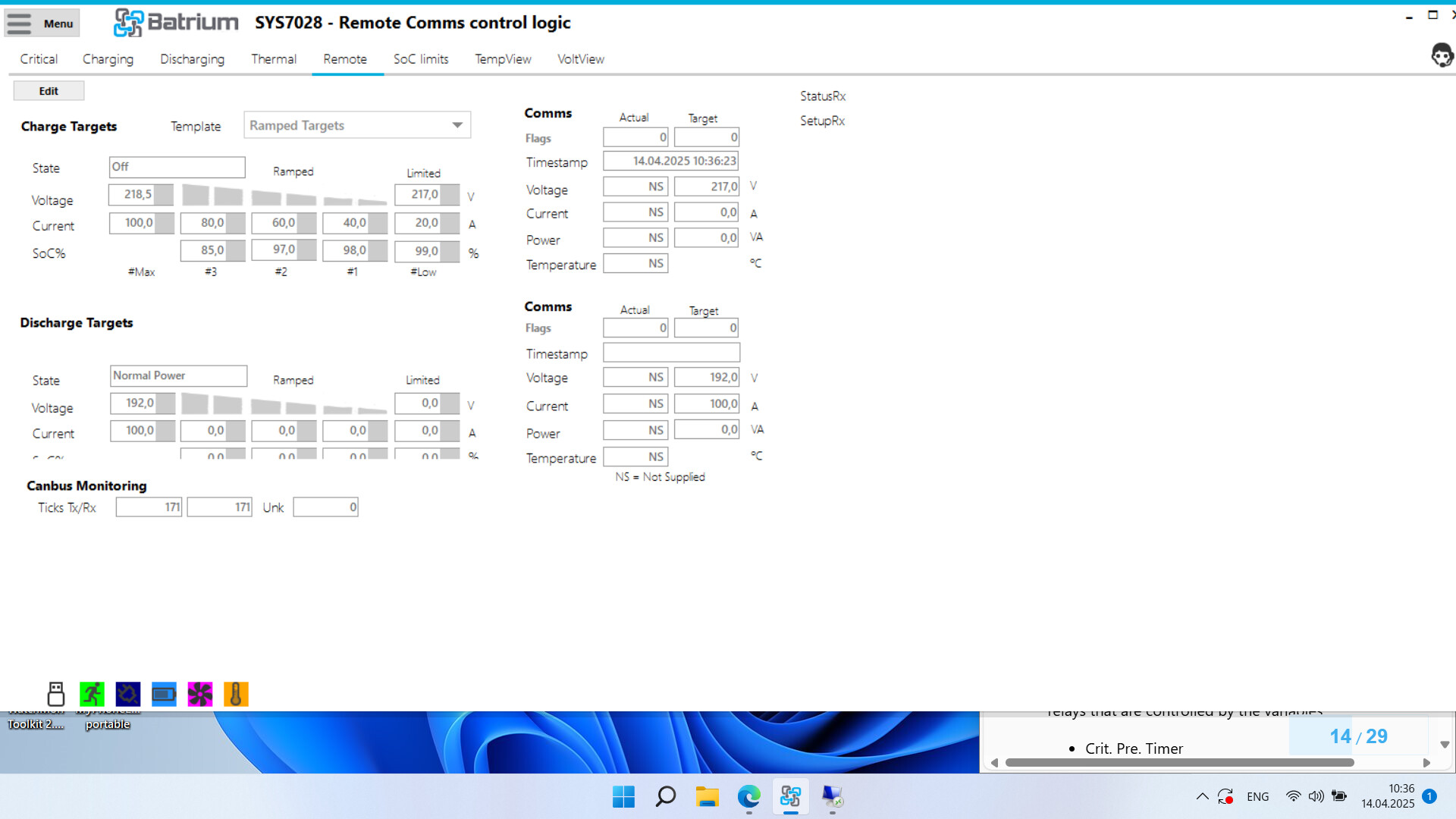
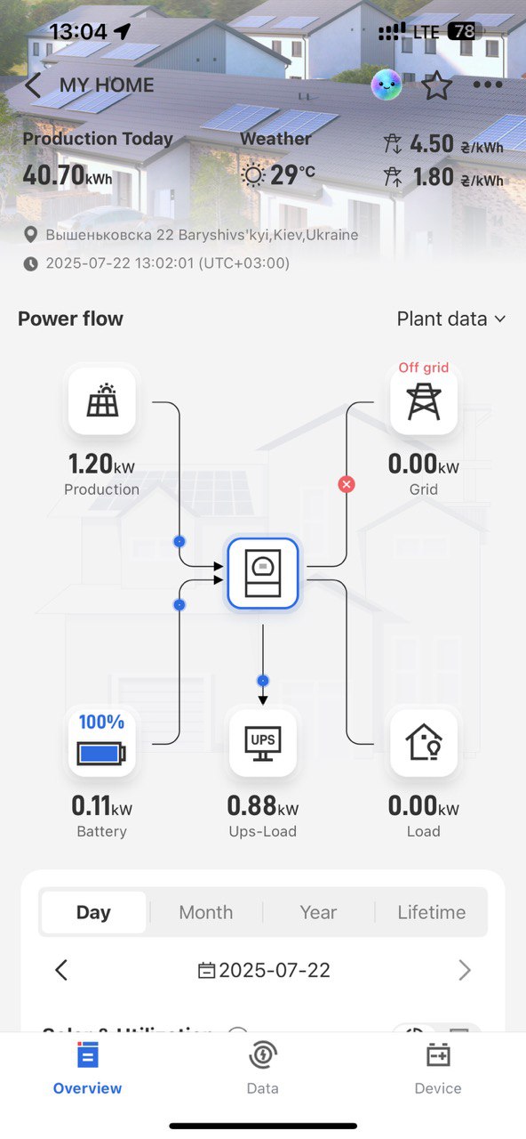
As for concluding the experiment, here are the new data points: When the battery enters the recharge mode, the Batrium sends the current charge target of “0” through the CAN bus to the inverter, but the inverter doesn’t disconnect the battery controller, and there is still a flow of around 15-50 W. This is enough for the balancer to struggle, and the battery slowly accumulates charge!
I see that the issue previously mentioned — where if the target is “0” the inverter delivers full power — is no longer present in the current firmware.
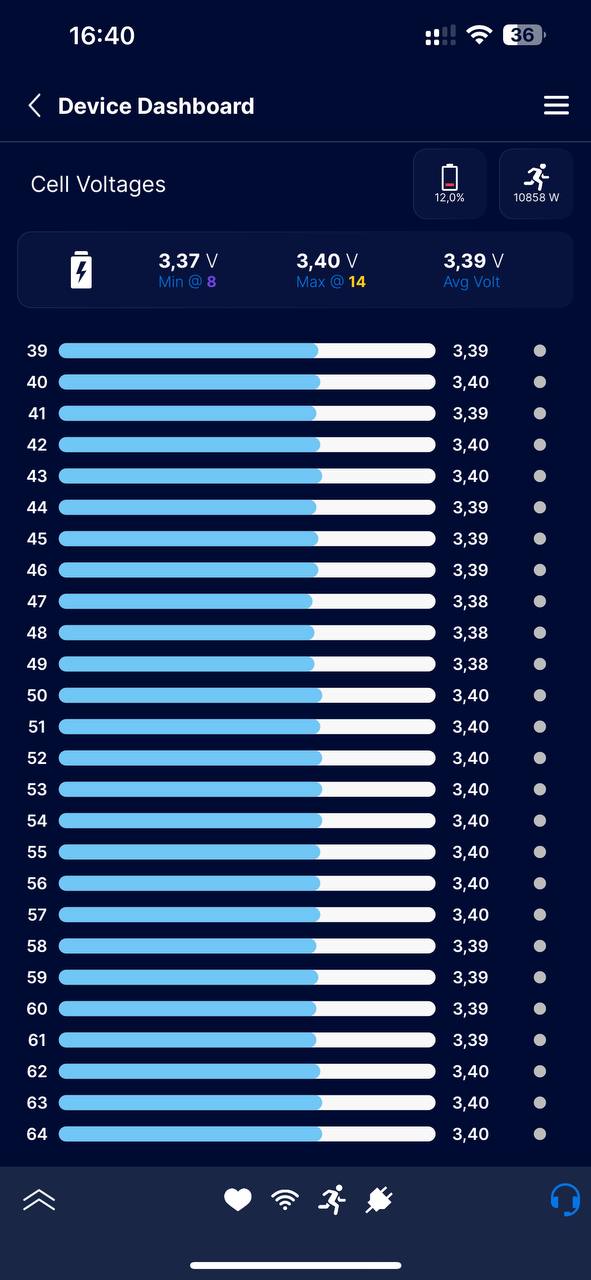
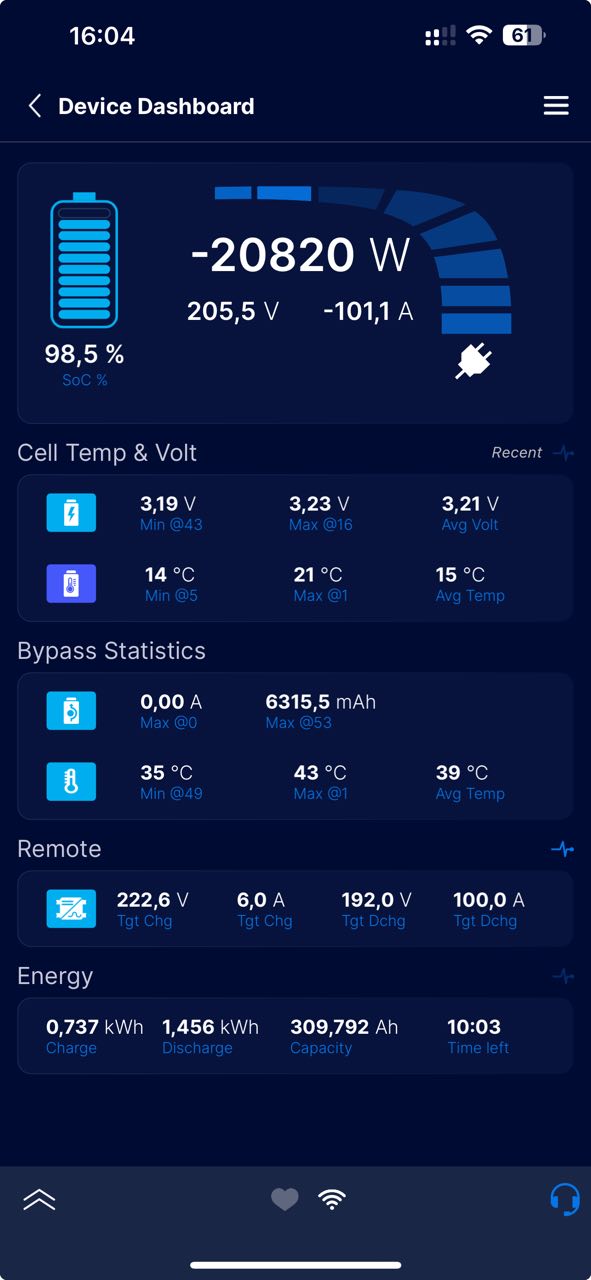
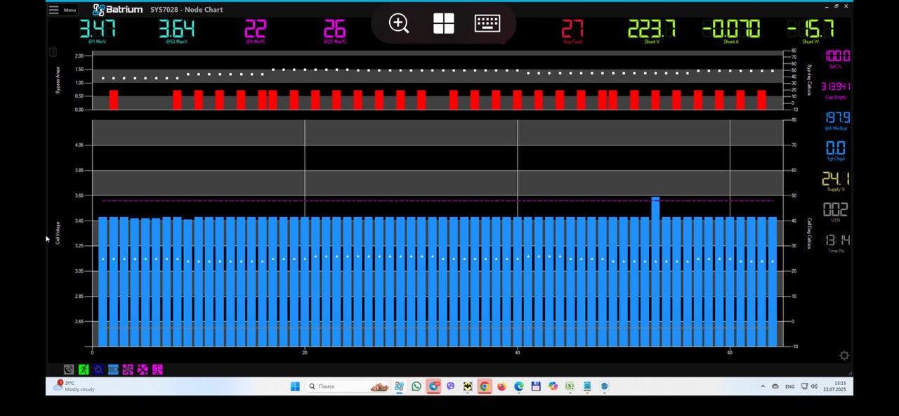
Here is a photo of the discharge test of the battery based on the Batrium BMS, thanks to the developers for the excellent device
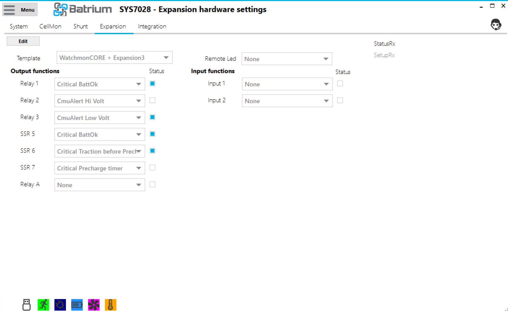
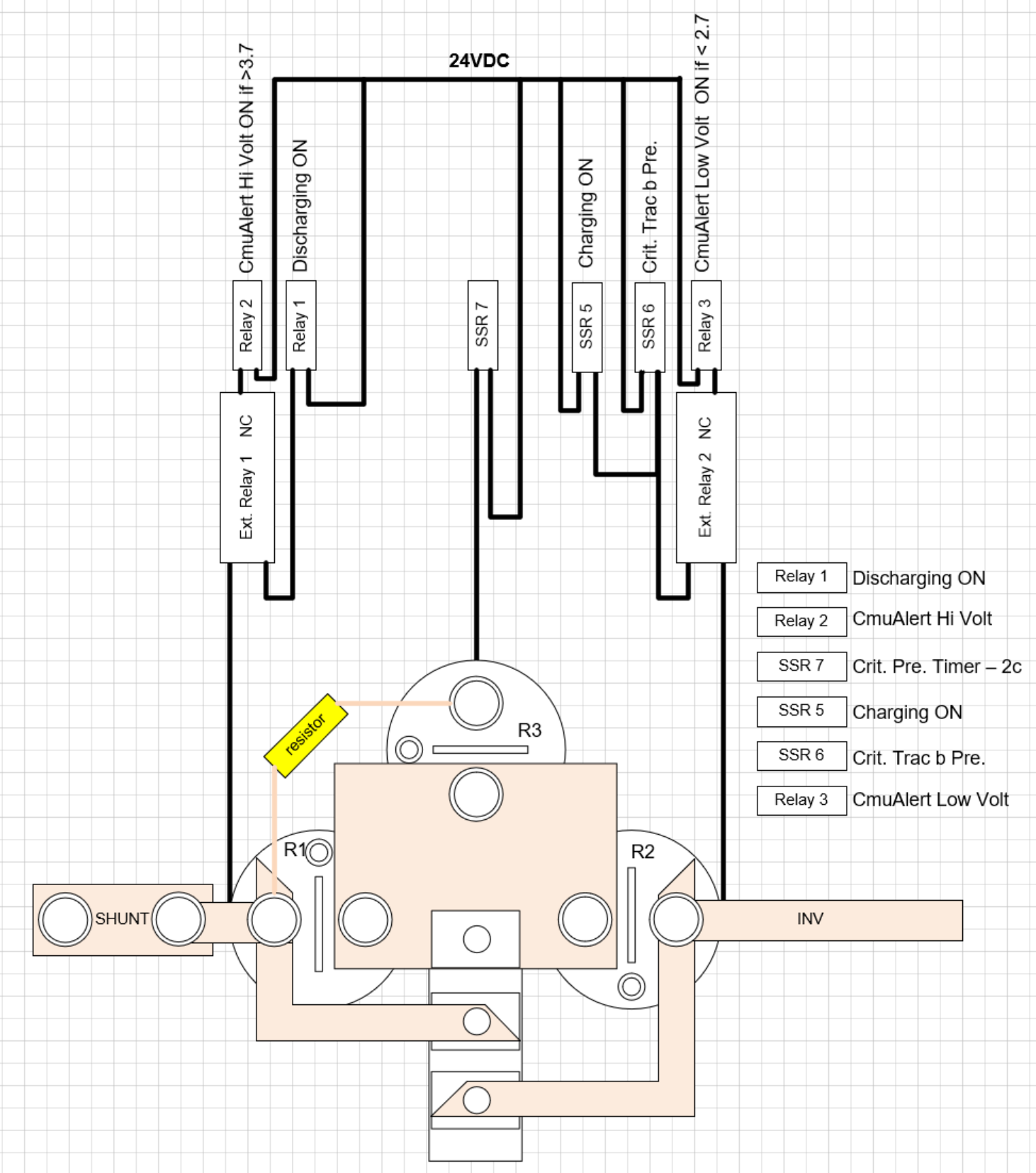
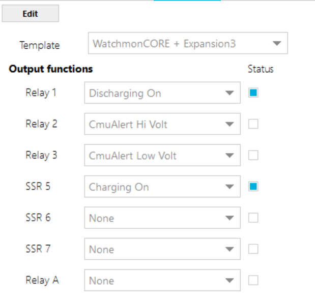
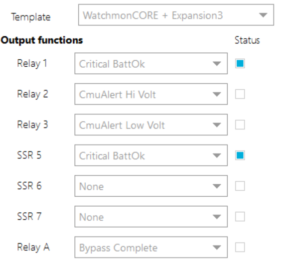
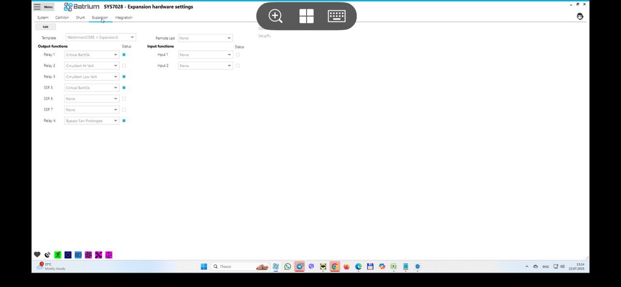
Here is the updated relay control diagram at the moment
precharge removed from the scheme for now
New from the fields ![]() Today the battery balancing was completed and I observe a completely different good situation.
Today the battery balancing was completed and I observe a completely different good situation.
Today I saw such a collision in the system operation (apparently James and Kleini warned me about this):
The previous relay shutdown mode was controlled by the statuses: charge off and discharge off. But when switching from the “charge off” mode to “charge limited on” the target for the charging current for the inverter does not become 0 and the inverter experiences discomfort when it is asked to give current but is not taken :)))
I continue to play and will share m
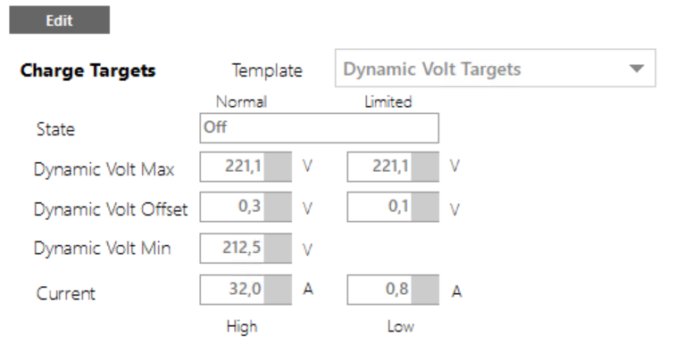
Batrium Dynamic Voltage Targets exactly provide a floating mode: Dynamic Voltage Targets
Previously, I used this setting:
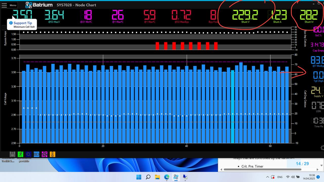
In my case, CmuAlert Low Volt is triggered (now they are inverted with CmuAlert Ni Volt) when 3.65V is reached for the most charged cell. This removes the voltage from the cells, while a small high-frequency squeak appears in the inverter (not the most pleasant). The balancer very quickly lowers the voltage below the critical 3.65 and the relay turns on again and so on all day long while there is solar generation.
It would be great to understand which trigger is tied to the value “Tgt ChaA = 0.0A” because if the battery charge limiting relay is locked and the inverter is sent a target value of the charging current different from 0.0A, the high-frequency squeak in the inverter is higher - I’m afraid it won’t last that long.
I assume that the “Charging Off” parameter will suit me
I’ll test it tomorrow and share my experience.
Today I switched to Dynamic Voltage Targets
and unfortunately it also does not exclude cell overcharging. The inverter still pours about 1A until it fills to the top ![]()
Wrote to the Chinese in support of Deye. Asked for an explanation why they do not stop charging the battery when the target current is 0? Also asked to tell the address of the register and the value that will transfer the inverter to the idle mode. (It is unlikely that they will write anything, perhaps if I were not just a client but a developer of the Batrium system, it would be more important for them to expand the compatibility list)
I have a table of Deye registers, it concerns a single-phase inverter, I will add it as an attachment, maybe someone will be able to get useful information from there.
Your cells are not yet balanced, and charge voltage limits are too high. You need to reduce the charge voltage limit to number of cells multiplied with 3.37V. Then wait until cells are full, and charge current goes down to 0A. Then increase charge voltage 0.1V and wait again until charge current is 0A. Continue until the first cell reaches balancing voltage. Then you need to wait until cell is discharged below balancing voltage and charge current is down to 0A. Then you can increase again by 0.1V and continue this whole cycle until all cells reach equally balancing voltage.
If all cells reach equally the balancing voltage you can return to normal operation. This is called serial top balancing and this must be done once or after long periods of not top balancing.
Once most cells reach their full state more simultaneously, the battery voltage will raise a lot when cells are full. It is then much easier to control the charge current to go to 0A just by limiting the charge voltage. Controlling currents whether they flow through the battery or through the inverter to the grid is hardly possible. Currents just use the path of lowest resistance and battery internal resistance is very very low.
I am in contact with Deye and they are in contact with BYD engineers. I also do not know why they do not power down their DC stage when target current is set to 0A. Hopefully this will be fixed in 1096 firmware release. Here the answer:
Blockquote BYD’s problem recently we have also developed new software jointly with BYD’s engineers. The new software is undergoing user testing. All power stations are running well at present. The BTD problem will be solved when the official version is issued.
we are already close to the firmware version you indicated, I already have MAIN: 3103-1095-1E08
Good day to all!!
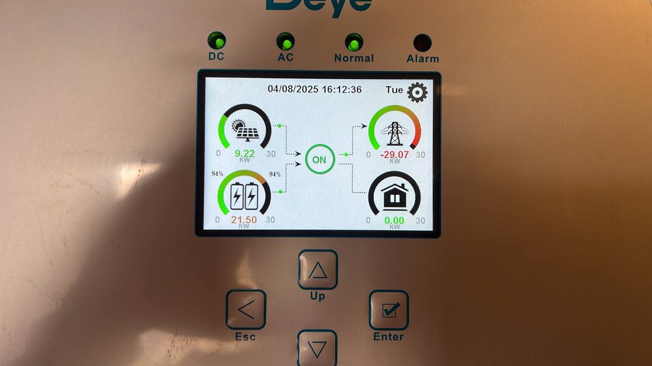
Today I encountered a situation that convinced me of the correctness of the battery piping scheme I had chosen to work with the DEYE 30KW HV inverter.
My inverter operates in the mode of exporting unused electricity to the power grid with priority on consumers.
description of what happened:
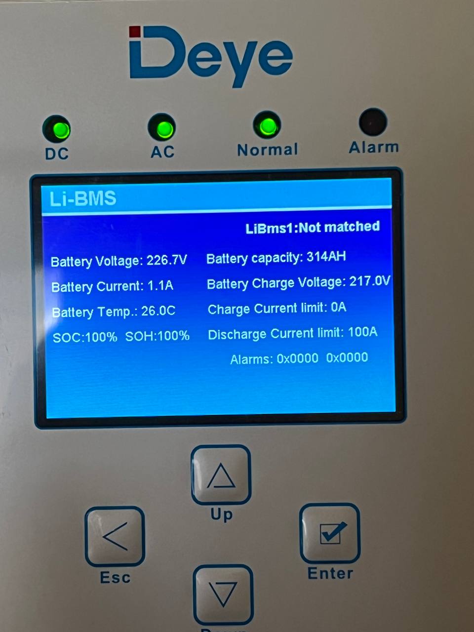
In the morning, when the battery reached 100% and began balancing, the electricity in the city network disappeared and the export was stopped. At the same time, the battery BMS had already made a request for a charging current equal to "0"A. But the inverter continued to pour out current little by little, despite the prohibition from the BMS.
Here are the screenshots
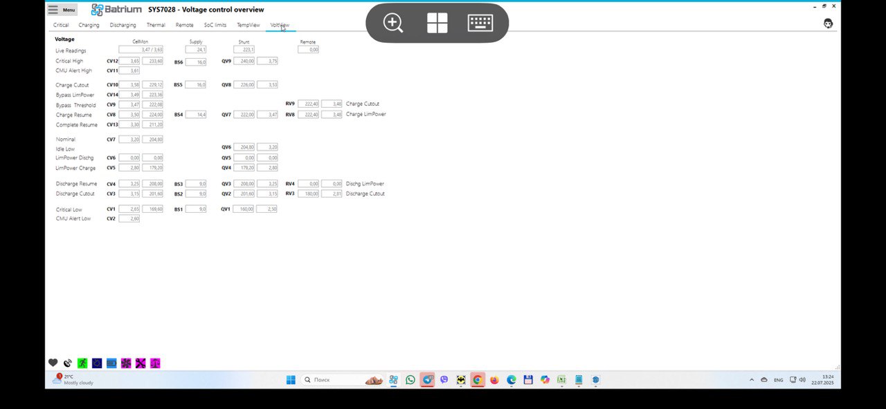
I would like to draw your attention to the fact that when the threshold values of “CmuAlert Hi Volt” are reached, due to the fact that the current target was 0 and the inverter did not really want to pour something into the battery!! the relay that was triggered to block the charging current without breaking the circuit that allows the inverter to discharge the battery does not cause an error in the inverter and behaves adequately.
For developers:
Please note that when CmuAlert Hi Volt exceeds 3.65V, the “CmuAlert Low Volt” trigger is triggered!!! This can be seen in the screenshot “3.jpg”
This is not the first time I have spoken about this error. If any algorithms are tied to this mechanics, there may be a problem with their operation at the most critical moment!!!
If the bug is fixed, please let me know so that I can also redo the triggers in the operation of the logic of my protective device, thanks in advance.