The battery I’m charging throws a critical error
I’m using Canbus native 2.0 protocol and via my app I have logged the critical and charging flags coming from the watchmon. This is on a 44V battery pack.
Log
CriticalFlag: 1 ChargeFlag: 1 DchgFlag: 1 HeatFlag: 0 CoolFlag: 0 CellBFlag: 0
Current: 45.44 Charger Voltage: 50.38 Shunt Voltage: 49.50 Status: 1
CriticalFlag: 1 ChargeFlag: 1 DchgFlag: 1 HeatFlag: 0 CoolFlag: 0 CellBFlag: 0
Normal Phase: Voltage present, Current within limits, Staying ON
CriticalFlag: 3 ChargeFlag: 3 DchgFlag: 1 HeatFlag: 0 CoolFlag: 0 CellBFlag: 0
CRITICAL ERROR 1
Critical Flags bit 0 & 1 are set.
From the native canbus 2.0 documentation "WatchMon - Canbus Native 2.0 messages " pdf
critical control flags, Bit 0 is OK state (relay state) , bit 1 is Transistion of state, and bit 2 is precharge.
What does bit 1&2 mean?
The C code I’ve inherited errors on any flag set other than bit 0.
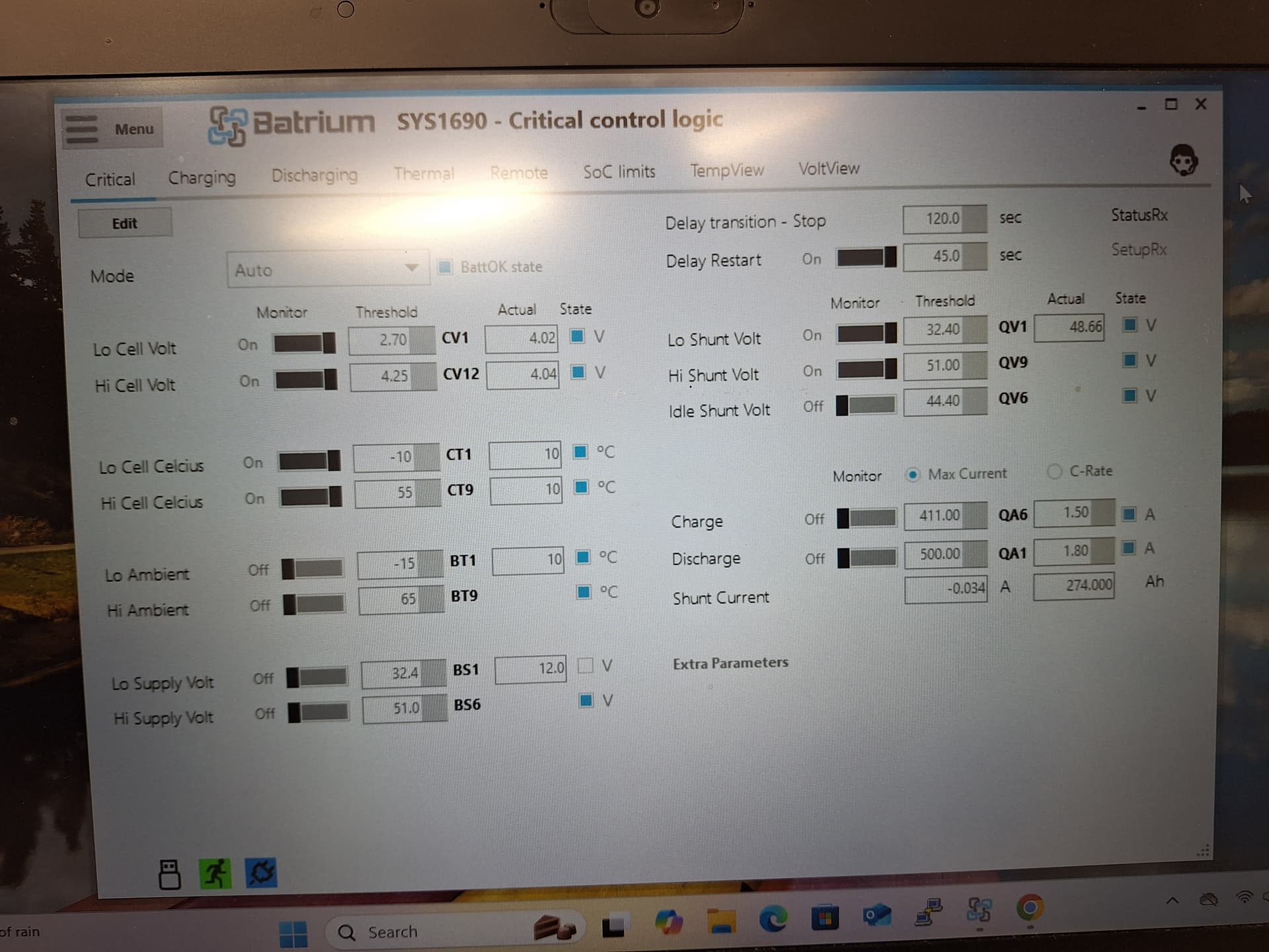
In the toolkit app no fields are highlighted in yellow to indicate an error
The tookit app did produce an snap shot which does refer to a critical error as below, but doesn’t seem to say what caused it.
===========================================================================
System 1690 - SYS1690
WatchMon1690
TimeStamp 7/2/2025 11:56:21 PM
System status information
Device Time Startup
7/3/2025 10:50:48 AM 7/1/2025 9:23:40 AM
SupplyVolt Ambient WifiSignal%
12.07v 24ºC Offline
Versions Hardware Firmware Software SerialNo
14.6 14.4.88 2.17.57 446913609
OpStatus AuthMode CMU Mode
Idle Default Normal
SysFaults: Nil
Live status information
Min @ ID Max @ ID Avg Repeat
CellVolt 4.00v @ 12 4.02v @ 1 4.01v 416
CellTemp 22ºC@ 1 23ºC@ 9 22ºC
BypassAmp 0.00A @ 0 0.00A @ 0
BypassTemp 27ºC@ 9 28ºC@ 1
BypSession 0.0mAh@ 0 0.0mAh@ 0
Total Overdue +Final +Initial InBypass
NumOfCells 12 0 0 0 0
SoC% Temp Volt Amp
Shunt 100.0% 38ºC 48.43v -0.019A
ToEmpty ToFull
Nom Capacity 273.986 0.014
Est Duration 33.8d 01:51
Recent Consume 0.020 0.008
Expansion board
Critical logic
control BattOK state
status OK
Charging logic
control ON state
Idle Bypass: off
status OK
Discharging logic
control ON state
status OK
Thermal Heating Logic
control OFF state
status OK
Thermal Cooling Logic
control OFF state
status OK
Remote Logic
ActV ActA TgtV TgtA state
Charge 0.00v 0.00A 50.30v 328.80A ON state
Dischg 0.00v 0.00A 40.80v 400.00A ON state
Daily Session information
Min Max
CellVolt 3.62 4.05
Thermal 12 23
ShuntSoc 57.5 102.0
ShuntVolt 43.75 48.79
SupplyVolt 12.00 12.04
Critical Events 1
Charge Dischg
ShuntPeak 47.09 0.00
Cumulative 121.452 0.166
Banding(hr) A B C D E F G H
SoC% 1.1 0.6 0.6 8.5 0.0 0.0 0.0 0.0
Thermal 0.0 0.0 0.0 0.0 2.0 8.8 0.0 0.0
Cell Node information
ID MinV MaxV MaxT BypT DatEr Reset RepCV
1 4.02v 4.02v 22°C 28°C 0 0 31
2 4.01v 4.01v 22°C 28°C 0 0 31
3 4.02v 4.02v 22°C 28°C 0 0 33
4 4.02v 4.02v 22°C 28°C 0 0 33
5 4.02v 4.02v -40°C 28°C 0 0 33
6 4.02v 4.02v -40°C 28°C 0 0 33
7 4.02v 4.02v -40°C 28°C 0 0 33
8 4.01v 4.01v -40°C 28°C 0 0 31
9 4.02v 4.02v 23°C 27°C 0 0 33
10 4.02v 4.02v 23°C 27°C 0 0 33
11 4.02v 4.02v 23°C 27°C 0 0 17
12 4.00v 4.00v 23°C 27°C 0 0 31
Bypass related information
ID Bypass Initial Session Amp
Cell Node setup
ID HiT HiBypT LoV Hi(V) BypV BypA CalV Serial HwVers
1 55°C 60°C 2.70v 4.23v 4.17v 0.60A 0 413461205 HW9.0 FW0.7 BL160.15
2 55°C 60°C 2.70v 4.23v 4.17v 0.60A 0 413461205 HW9.0 FW0.7 BL160.15
3 55°C 60°C 2.70v 4.23v 4.17v 0.60A 0 413461205 HW9.0 FW0.7 BL160.15
4 55°C 60°C 2.70v 4.23v 4.17v 0.60A 0 413461205 HW9.0 FW0.7 BL160.15
5 55°C 60°C 2.70v 4.23v 4.17v 0.60A 0 413461205 HW9.0 FW0.7 BL160.15
6 55°C 60°C 2.70v 4.23v 4.17v 0.60A 0 413461205 HW9.0 FW0.7 BL160.15
7 55°C 60°C 2.70v 4.23v 4.17v 0.60A 0 413461205 HW9.0 FW0.7 BL160.15
8 55°C 60°C 2.70v 4.23v 4.17v 0.60A 0 413461205 HW9.0 FW0.7 BL160.15
9 55°C 60°C 2.70v 4.23v 4.17v 0.60A 0 413461205 HW9.0 FW0.7 BL160.15
10 55°C 60°C 2.70v 4.23v 4.17v 0.60A 0 413461205 HW9.0 FW0.7 BL160.15
11 55°C 60°C 2.70v 4.23v 4.17v 0.60A 0 413461205 HW9.0 FW0.7 BL160.15
12 55°C 60°C 2.70v 4.23v 4.17v 0.60A 0 413461205 HW9.0 FW0.7 BL160.15
===========================================================================
Any help appreciated.
Thanks
Graeme