Victron CerboGX/Multiplus II 3K - actual values NS?

Hey all, went the the docs and saw that it states

“Not all the Victron product transmit back the optional actual values. Hence we cannot display these values if they are not transmitted from the GX.
The communication is not at fault, verify that the GX is sending the heartbeat RX timestamp to confirm communication is functioning properly”

I wanted to see if anyone here can confirm or not for me that their own Multiplus II is either sending or not sending values I’m missing back to the WMC? I don’t have another system to compare it to for troubleshooting.

Thanks for the info!

Running

WMC
CellMon
ShuntMon
CerboGX
Multiplus II 3K

1 Like

I also wanted to add and ask about the function of “remote” I’m wanting to use the “ramped down” settings and I assumed that it would give me the current specified above the current used in real time.

Example, I’m using -10A from my bank but I want to charge at 50A and in reality I’m only charging at 40A because the WMC isn’t adjusting the CCL in the Cerbo to compensate for the extra 10A being used? Am I correct in assuming this is wrong and not working correctly? With the default settings for “ramped down” I would never be able to charge my bank fully because I’m always going to be pulling more than the final “stage” allows which is 0.6A.

Looking for anyone who can assist with this, the Batrium system is a little confusing at times.

I do have the same info with MP-II 5k

Are you using the “ramped down” feature and is the WMC dynamically adjusting the CCL on your cerbo?

Yes I do.
See results of the Victron

It’s hard to tell from your graph but is your WMC adjusting the CCL or CCV in increments that match ramp down settings but taking the actual load into consideration?

Example: If I have the WMC set to tell the cerbo that at 90% I want the charge target to be 100A and my load is 50A then the WMC needs to tell the cerbo to make my CCL 150A but in actuality it’s instructing the cerbo only to the 100A which leaves me with a 50A charge current.

Can you or anyone confirm the same for me?

Does anyone from Batrium follow these forums?

@James

Hi t37x609,

Unfortunately most chargers take as much as 1min to respond to limit changes, there’s no way we could create a usable control loop with how quickly loads can fluctuate. These values are simply for reference.

Unfortunately because Victron systems are broken into separate parts (inverters, chargers, controllers), Victron expects the battery to somehow know what the load is and tell the charger what to do accordingly, other inverters simply modulate their MPPT based on the load. I can draw diagrams if you need this clarified.

Their ideal is for us to never control current, leave it at full all the time, and modulate the voltage target dynamically in reference to the battery voltage. We are working towards this, but it is different to every other manufacturer on the market.

@James

That’s unfortunate to hear. I wish I had known this limitation before diving in with the Batrium system. Knowing this now it seems Batrium is not a good choice for a mobile environment where DC loads can change dynamically and it should be used for ESS systems only. With the limitations outlined I’d never be able to finish a charge cycle if my loads interfere with the non dynamic charge settings.

Take a look at this piece of software. I was able to achieve what I’m describing with this driver and a mosfet based BMS but needed to go to a contactor based system for higher amps when moving up to a larger inverter.

I understand this interfaces entirely different but it was able to adjust CCL in very small amounts accordingly to my loads and did so in real time, the chargers obeying DVCC rules had no issue changing their charging within seconds.

Hope this post helps others, please consider outlining these limitations in the documentation as I was caught off guard by this after my purchase.

Hi t37x609,

I believe you should be able to configure our system the way you want.

Please send us a Manual Extract via email and we can take a look at your charge targets and bypass thresholds to get closer to what you want.

I understand sun is precious in a marine application, we may be able to get close or right on what you want.

First of all, Batrium tells the Victron system something about a limit, which is a maximum not a target. You’re misinterpreting this charge current limit as target charge current.

Can you please describe your use case a little bit more? I read “mobile environment with DC loads”. Are you trying to charge batteries through a Victron inverter/charger from domestic power? Did you configure an ESS system? If you’re trying to charge batteries from domestic power, you need to adjust target state of charge in Victron system, not CCL in Batrium. Unfortunately, I am unfamiliar with such a setup. I would say, you need to change in ESS settings the mode to “keep batteries charged” and then the Victron charger will charge your batteries with maximum allowed current (CCL).

You’re right about the CCL and CCV being a limit and not a target but also we can see a trend where the BMS is evolving into more of a “central” charge controller so all charge sources are on the same page and that driver I posted uses the limits as a target in a sense. I was hoping Batrium would do the same. For me and my use case where all my loads can be DC loads all the time I need a BMS that takes current load on the battery into account when calculating the CCV/CCL limits. ESS doesn’t apply to me because there are long periods of time where I’m not connected to the grid at all and it’s not how I’m using my system.

The Batrium system is perfect for a stable system that takes in grid power during the day and uses battery at night, with no DC or very stable DC loads.

I went with Batrium because in early emails with James I was told " We currently offer dynamically adjusted current control as this is the standard approach for a lithium chemistry to match the cell manufacturers recommendation of CC/CV charging." and I assumed that meant it would take the loads into account, however I understand now he was simply referring to the “ramp down” feature which I suppose is dynamic but in a limited sense.

Ether way this good info for the community and for Batrium to take in and no shade on Batrium the product itself is pretty top tier just not a good choice for an RV/Marine setup at this time. Perhaps in the future focus could be put on making some changes that would change that, RV/Marine is a big market with people flocking to LiFePO4.

@t37x609, I am sorry, to have to say this in direct words: You’re looking for your desired functionality in the wrong system component. A BMS protects your battery, nothing more, nothing less. It monitors the essential values like pack voltage, cell voltage, charge or discharge current for state of charge and temperatures. You can define maximum and minimum values for all of these and Batrium tells you, whether your battery is okay or not. Furthermore, it tells the other system components how much can be charged or discharged. And that’s all.

What you’re expecting is: MultiPlus transforms from AC to DC the power you’re requiring to charge the battery with constant current plus powering your DC loads, which may vary. Batrium does not know anything about DC loads. You need to place a Victron shunt to measure DC loads and its measurements are transmitted to the GX device. There may be solar charger, which can also provide DC power powering your loads and/or charging your battery. And maybe much more devices. All those devices need to be known to the GX device. The GX device can then control, what the MultiPlus does. And that is exactly, what happens in an ESS system.

According to this: https://www.youtube.com/watch?v=zIfRHrxtxKo&t=1615s mostly all Hub configurations seem to be pretty deprecated. So, you’re correct to configure an ESS system.

If you’re now connected to the grid and you want to charge the battery, then you have two options:

  1. Change mode in ESS settings in the GX device to “Keep batteries charged” and the GX device will instruct the MultiPlus to charge the battery with CCL rate.
  2. Configure in ESS settings in the GX device "Minimum SOC (unless grid fails) to 100% and the GX device will instruct the MultiPlus to charge the battery with CCL rate.

So, you configured your system correctly and you still have the possibility to charge your batteries when connected to the grid.

@kleini

I’m not sure you read my response or if you did I don’t think you understood it. Your explanation of my needs and desires is incorrect. I don’t need anything to do with ESS and my system should be considered “off grid”.

I mentioned above that the idea of what a BMS is, is transforming into a central charge controller. A lot of manufacturers are starting to go this way and users are wanting this, visit any other forums and it’s what people are talking about. JK BMS just released what they’re calling an “inverter BMS” which does exactly what I’m talking about. The idea is that the battery is the sole driving factor in determining voltage/current under outlined specs and because the BMS is the source of that knowledge it’s not a hard leap to understand that you’d want the BMS to “instruct” other charging sources how to charge at a given time. Thus becoming the central or “master” controller in a system.

Battery systems are always changing and new ideas and concepts are always coming into play. The future of BMS will have a role to play in dictating charge parameters and no simply being for battery protection.

Either way, because the Batrium software does not or cannot dynamically account for load when supplying CCL/CCV limits to VenusOS it’s not going to work for my needs at this time. It’s a great piece of kit but I was misunderstanding its limitations and my questions to James weren’t specific enough before I bought into the system. Mainly still responding here so when others web search the system they can have a clear understanding of what it can and cannot do.

@t37x609 I read your response. And I totally disagree. JK is going the wrong way. A BMS is not in charge to know about any load or power source. And there can be a lot of them. For the Victron eco-system the central controller is the GX device, and I am glad, it is this way. This allows me to add more varied loads and additional power sources.

You’re running not running an off-grid system. In Victron terms you’re running a backup system. An off-grid system is always without grid. You’re not.

I understand your drive, integrating systems more and more to reduce the need to have so many components. Still, Victron is then the wrong choice for you. Their philosophy is to have many and universal components to build up systems. This is complex, and complexity is not for everyone.

Btw. it is charge current limit (CCL) and charge voltage limit (CVL) not CCV. I am sorry to say it so harsh, but you have chosen the wrong system components for your desires.

1 Like

@kleini

It never ceases to amaze me the internet keyboard warriors that think they know so much. My system is off grid because I’m designing that way for my personal desires and plans. Planning to use the grid would be against my goals.

Yea the Cerbo is the central hub for Victron chargers, but the BMS has the knowledge (individual cell data) and the Cerbo sets the limits based on that. That’s just a fact, I would love it if Victron had a sophisticated way to control charging from the Cerbo and take in cell data like a BMS does but they do not. It’s funny to me how you claim “JK is wrong” they are simply responding to what the market wants and people want their BMS which is already the sources of knowledge about the battery to direct charging of that battery. It is what it is and actually makes sense if you aren’t so stubbornly stuck in an old idea.

Either way, you are correct. I do have the wrong system for my BMS to accomplish my goals. Also thanks for the correction about CVL, I might have died without it.

Saying it again… the Batrium BMS is a great BMS for ESS systems. Simply because the WatchMonCore/CellMon/ShutMon does not take real time load into consideration when applying the “dynamic” ramp down current means that someone who wants to apply a low current near the end of a charge cycle so cells have a chance to balance cannot do so, because the loads on the system are always fluctuating and will often rise above the value set for “ramp down”. I’m in no way knocking Batrium, just pointing this out so others who google this feature will have a more clear understanding because I did not based on Batrium’s provided information.

I’ve said all I need to say on this topic I believe and don’t want to turn this into anything more than it is. I hope I’ve illuminated this topic well enough for anyone interested that comes across this thread.

Where are your 50A coming from charging your battery with only 40A if not from the grid, that should be 60A?

Where are your 50A coming from charging your battery with only 40A if not from the grid, that should be 60A?

There are other charging sources other than the grid… mainly in my case solar and engine alternator.

Regardless of where the energy comes from you’re missing the key point here. It’s that a system with fluctuating, let me bold and highlight that for you fluctuating DC loads needs to have a dynamic (meaning it changes) charge source. My system even when I am docked has fluctuating DC loads and having a preset charge parameter does not work because my fluctuating DC loads could rise higher than the preset charge rate and result in me not actually getting a charge. With LifePO4 we want a small current near the very end to allow bypass/balancing to happen. The CellMon is only able to bypass at 0.60A and ideally that is what we would want our charge rate to be at the very very end of the charge cycle. 0.60A would be overwhelmed and made null if I simply turn on a light.

Do you understand now?

Solar power and an engine alternator may not provide the power you require to power your loads and charge your battery. So, this problem will always be part of your system design and during balancing it will happen, that you do not have enough power to maintain a full battery.

Besides that, my opinion is, not to charge batteries always up to cell voltages, where balancing is possible to take place. See this article for details: Charging Marine Lithium Battery Banks | Nordkyn Design Keeping cells in voltage areas for balancing over long time, overcharges the cells and therefore destroys their cell chemistry and capacity.

This is both to get your expectations right, to explain my solution to your problem. I would not look at charge currents anymore. In your case, it will be impossible with nearly constant charge currents from PV and generator to get constant charge currents for your battery with non-constant DC loads.

Instead, start looking at charge voltages. One reason is the above article about correctly charging Lithium cells. Another reason is the physical impossibility to create constant charge currents towards your battery with three sources or sinks of electricity in your system: PV, battery and DC loads. My system is similar: PV, battery, AC loads and grid feed in. In my case, Victron documentation is clearly stating, that CCL is ineffective with feed in from DC. DC coupled PV needs to provide full power, as much current as possible. And this current either goes into the battery or is feed in into the grid by the MultiPlus. So the split between current through battery and through MultiPlus can only be controlled by the voltage. Your PV power goes either to your DC loads or to your battery. Only the voltage decides, where it goes to.

And here comes the physical why: The more full your cells get, the more the cell chemistry is not able to push any more Lithium ions from kathode to anode, the cell internal resistance rises and therefore cell voltage rises.

Now, configure your charge voltage to 3.37V per cell (float voltage). That is the area where cells can remain the whole time without being overcharged. That’s how I do it. And then from time to time, when state of charge is already at 99% and charge current is already 0A and your PV has to reduce power, raise the charge voltage to 3.45V (minimum for balancing) and look at maximum and minimum cell voltages until they have only a difference of 0.1V and your cells are balanced. You can then reduce charge voltage again to 3.37V per cell to not overcharge them.

This cell voltage based top-balancing is unfortunately not supported by Batrium. It is also not supported by any other currently existing BMS on the market. At least I don’t know of any. Batrium only looks on “Bypass session” CA3 for every cell. Every cell needs to be “balanced” by CA3 mAh and then Batrium considers battery as fully charged and state of charge jumps from 99% to 100%. Instead the cell voltage difference should be the right trigger to consider a battery as fully charged. And only if cell voltages are at “Bypass Volt” CV9. @James Please consider this charge termination condition in Batrium software once in a future version.
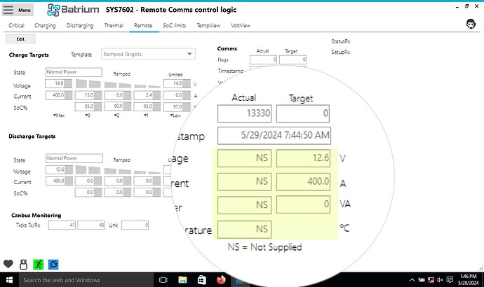
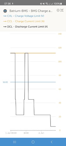
@kleini, you still don’t get it my man, at this point there are no words that I can provide that would help you.

I’m going to bow out of this conversation as I’ve invested in another BMS/software that provides what I need, Dynamic charge control based on real-time load and MQTT.

If anyone in the US wants to buy my Batrium system please send me a PM.

Consist of
01-WMC
01-Expansion
01-K9
01-Shutmon

Several 500A contactors @ custom made extension cables for the shutmon/k9 to mount remotely.