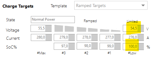
The ramped targets UI in Batrium is not intuitive . Also the ramped targets feature is IMHO (and Victrons) built the wrong way. The correct way to control charge current is by varying the target voltage.
I believe Batrium are working on this (YAY) - and hopefully it will come with new Ramped targets UI that makes more sense.
I’m not sure I have any of this right, but I’m going to repeat some of my own [mis]understandings.
I think there’s 3 notable “ways” in which my Victron inverter/charger may deal with ‘a battery’.
(I’m really speaking nearly entirely about the charging function here, which is most important to me. The inverter part is secondary, as a motor is my primary consumer of power.)
dumb battery / default ; For many folks, the inverter/charger and battery do not communicate. The charger simply follows an algorithmic bulk/absorb process for lifepo4.
Can-bus connected “the old way” ;
I understand that the Batrium BMS can utilize the SOC state as determined by the shunt, and can alter “target limits for the Victron equipment to follow.” , which may yield a “ramping down” of current toward the end of charge.
DVCC standard from Victron.
I believe this is the successor to #2 . This is also how I perceive the “correct way” to be.
I’m not positive this even handles the ‘ramped’ charging situation - but it does seem to take into consideration max rates of charge from multiple devices.
Now, I have a simple system I’m creating.
But I’m stuck on the idea of trying to use DVCC (ie, buying a competitor’s product), because it sounds more like what I would expect to be ‘correct’.
I may be greatly overthinking all of it. I’m curious if I’m even thinking about the right issues in the right ways (being kind to the battery at the top end of charge). Any comments would be appreciated.
If you’re using the #2 option, Victron Cerbo GX interface to CAN bus, another way to approach floating would be to load the Venus OS Large firmware image in to the Cerbo and use Node Red. I use a Node Red script to lower the DVCC voltage limit to float setpoint after the pack reaches the BMS target voltage for several minutes. The script raises the DVCC limit once a certain SOC limit has been reached.
@wireslv - thank you very much! I feel I hijacked the thread, and I will continue to do so…
What would I lose if I do not buy any shunt to integrate with Batrium ,
and instead just let my existing Victron smartshunt talk to my Cerbo GX, which in turn controls 48v multiplus2 inverter/charger ?
If I want access to cell level voltage/ BMS diagnostics (fixed display and/or smartphone display), what are my options such a Batrium & Victron Cerbo GX based system?
I have a raspberry pi with a CAN hat that I’m prepared to use if I must. But it would seem node red on the cerbo could do all the things.
Thank you again. Your comment helped me tremendously.
I think I may have found my people in this forum, and it’s given me increased confidence in Batrium’s products.
I used only the Victron shunt for a while and works fine. However the SOC data from the Victron equipment does not get written back to the Batrium BMS. I wanted the SOC ramp-down functionality during charging, so I added the Batrium BMS at a later date to the sytem. Now I have both. The Batrium shunt seems to be more accurate so that is the value I use for control.
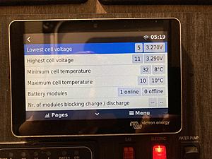
The Cerbo GX will display the min and max cell voltage and also temperatures.
I’ve added an enhanced version to the onedrive location which includes user-configurable settings on a dashboard and also implemented DVCC current ramp-down.
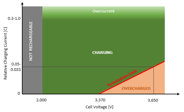
This diagram shows the charge termination limit for LiFePo4 cells. Every cell voltage above 3.37V results at that point in overcharging the cells when the charge current drops under the termination limit. So that maximum voltage, a LiFePo4 cell may rest longer times, is 3.37V or less.
So it absolutely makes sense to drop charge voltage to 3.37V after top balancing cells to avoid overcharging and therefore destroying the cells.
Thank you for the pic, may I ask for the source?
Anyway, let’s assume float makes sense and I want to set it to 3.35V.
If absorption is done to 3.45V and I switch to float, the cells will be discharged down to 3.35V.
Why should I charge then to 3.45V if I discharge them immediately to 3.35V?
Doesn’t it make more sense to set absorption to 3.35V and do not float?
Absorption is a term for lead acid cells. It does not make any sense for LFP cells.
I am not doing top balancing on LFP every day because that would mean to overcharge the cells every day. I am doing top balancing only once every month.
Top balancing only once a month is currently not possible with Batrium. I am integrating Batrium with a Victron Energy ESS system. Within that system, I can configure a max charge voltage and the least of that max charge voltage and the charge target voltage of Batrium wins in the system. So once a month I remove that max charge voltage in my Victron ESS system and do top balancing of the cells.
With the current version of Batrium software you are unable to configure a float voltage setpoint. The BMS will only provide the maximum charge voltage setpoint. If you need a lower floating setpoint that will need to be configured on the charging system itself.
On a Victron system and this could be handled a couple different ways.
One would be to wire relay outputs from the BMS to inputs on the inverter and/or MPPT controller to indicate when charging is allowed. Then the Victron devices would follow their configured absorb/float setpoints.
Another is to use CAN bus to enable/disable charging and provide a maximum voltage setpoint. However when this method is used the Victron equipment won’t change over to float by itself, so custom programming such as a Node Red script loaded into the Victron Cerbo device will be required.
Ideally, either the Batrium software or the Victron software would natively allow a lower float setpoint to be used after the charge cycle has been completed. However that is not the case today.
I know, there are several workarounds possible, but imho it is a task for the BMS to handle the charge algorithm and guide the other components to behave correctly. Therefore the question is more directed to the Batrium team. I know, that they are working on a better Victron integration, but wish, there would be more transparency from their end.
Cheers, luphi