Help with Battery/charger wiring/contactor design for EV

Hello! I’ve received my Batrium BMS a while ago (Core, 2x K9, Shunt, Expansion) and will start building my battery next week. I am unsure about some aspects of my planned design so hopefully someone can chime in.

Parts:

  • 32x 280Ah LFP in series, two physical boxes
  • Batrium as above.
  • 3.3kW TC / Elcon charger
  • Sevcon motor controllers, Victron GX.
  • three contactors, two of which are controlled by the Batrium. The other main by the Sevcon.

My questions:

  • the Batrium instructs the TC. There is a contactor connecting the TC & Battery B+. Will the closing of this contactor create a big inrush current in the TC’s output cap ? Can one add logic on having the TC precharge to the battery voltage before closing this contactor ? How is this accomplished?

  • can the Core also function as an AP? Or only work connected to an already present WiFi network? / can one connect Ethernet through a USB adapter?

  • will having the contactors in the same physical metal box with the K9 create too much electrical noise for it?

  • are flyback diodes / snubbers / precautions needed when using the Expansion’s relays to switch contactors (powered by the same 24v PSU). Any recommendations on these parts?

Thanks! I hope everything will physically fit. Using ‘standard’ Chinese home ESS boxes in the boat, with some extra high feet.

Best
Wout from NL

Hi Wout,

Great questions, Let’s see if I can help!

My understanding is that the TCs will not energise their output unless everything is OK (battery is connected, correct polarity etc). There is usually an output on the TC for a contactor that it will connect when it is ready, and has been allowed to charge over CAN by Batrium. Could you confirm whether this exists on your charger?

The Core will function as an AP if it is not configured to connect to an external AP, or if it can’t reach the one it is configured for.

We haven’t had any reports of contactors causing too much noise for our equipment.

Flyback diodes are a good idea. Some contactors have inbuilt electronics to handle the spikes and also reduce energy consumption while being held closed, so see if you can find out whether yours do. Just something with a big chunky package is best to absorb the energy. It also depends on how many times this will switch, relays can still work with inductive loads, it just shortens their life.

If you have trouble getting the boards into your enclosures, remember you can take the PCBs out of their green plastic, and shorten any cables you need to, just be very very careful with the pinout if you make your own cables. Also be careful that metal objects are not going to short out the pins on the back of the board if you take it out of the green plastic.

Let me know if you need anything else :slight_smile:

Hey James, thanks so much for your response!

I’ve made some progress but this only comes with more questions!

I’ve contacted TC and they say there is a contactor and precharge circuit built into the TC 3.3kW charger. I would use a contactor inside the battery case anyway to not expose any live pins when the BMS shuts down. Is it possible to close this contactor when the charger is online on CAN?

I could use the 12v5a output of the charger to signal the BMS, but of course it would need more physical wiring.

I’ve been going a bit into the communications options over CAN; I would ideally have the following:

  1. TC charger over CAN 250k
  2. Victron comms over CAN 250k
  3. Communicate with my Sevcon Gen4 motor controller over CAN 250k

Is it possible to combine CANbus protocols ? (So comm with both the TC and the Victron over the same CAN)

I’ve found the CANbus page (Inverters & Chargers | Batrium Knowledge / Wiki) and the doc with CANbus messages; are these TPDOs being sent even when selecting another CANbus protocol?

My Sevcon motor controller has flexible CAN messaging and I can set it up to receive various CAN messages - if the values correspond to whatever the motor controller expects:
(BDI = battery discharge indicator)

% BDI remaining charge Unsigned8 0 FFh 0 1% / bit
A Maximum battery discharge current Integer16 0 32767
A Maximum battery recharge current Integer16 -32768 0

If you would be keen to include a profile for the Sevcon motor controller (or the ability to combine protocols) I’d be a happy camper! If you would like to see more on how the sevcon organises flexible protocols let me know I can show you around a bit.

If you would like I can also fill in the custom protocol request

Or is there a way for me to write custom firmware for the BMS myself?

Thanks a lot!

Best,
Wout

Hi Wout,

Glad to see you have made some progress, and I have read that info regarding the SevCon.

It is certainly good that you are able to customise the SevCon. Is it possible (for now) to have discharge current set as a constant, and regen as the payload sent to the Elcon?
Its structure is:

ID: 0x1806E5F4
maximum charge voltage 16b (high then low)
maximum charge amps 16b (high then low)
Disable charging 8b (boolean)
padding 24b

What role does the GX have in this case?

If the SevCon has a standard or out-of-box protocol, we would be happy to implement it fully. Alternatively, if you want a combined Elcon/Sevcon hybrid we can probably make that happen too. We are in a bit of a feature freeze while we work on our apps and other initiatives, so it may take a while.

We do also have a native protocol that has EVERYTHING in it, if you are open to have a device with two CAN interfaces sit in the middle.

Let me know what you think.

Hi James, thanks again for your reply.

The Sevcon won’t be online during charging, so it cannot be used for this purpose.

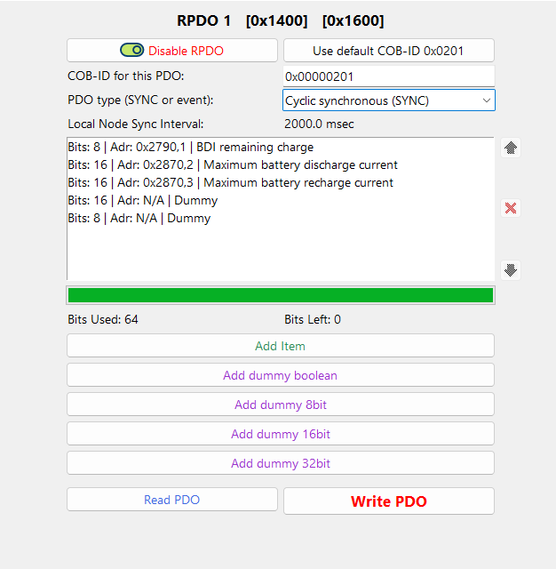
The Sevcon does have a ‘standard’ object dictionary and you can read and write to these depending on the access level. The BDI remaining charge has no access level and could be written without programming PDOs.

This is completely separate of the programmable PDOs (which is a cyclic transmit data and possibly receive data). There are no predefined messages for this, however it’s very customisable so we/you could create a frame which can be received by the Sevcon, call it the new standard and post it on the Wiki. I think this would be preferential. Probably just the BDI would be sufficient, the other values can be set or be dependant on BDI%. They might be interesting once the battery reaches temperatures which are outside of spec if derating can be programmed into the Batrium.

The Sevcon can independently estimate and map battery% based on the battery voltage, and cutback when this is below certain voltages / estimated %. However for an LFP setup I expect this to be quite far off in the middle 80% of the capacity range. To prevent pulling 400A at a low SoC it would be ideal to communicate the battery% beforehand.

The idea of the Victron was to only read out data from the Sevcon (there’s a plugin made for it) and Batrium and show these on display. I haven’t got it yet and the idea is to not need it for an MVP either.

So ideally the Batrium would control the charger completely and then also transmit the full package every now and then to be received by the Victron. Ideally including a custom frame for the Sevcon to control the BDI.

Some more questions regarding physical stuff, which I hope you can answer!

My idea was to have a key switch which then closes a relay if the BMS allows discharge. This will be the actual ‘key’ input for the motor controller(s). The main power contactor will be driven by the motor controllers (as this may only close if the motor controller allows it and has charged the bridge)

ideally if the charger is online (and charging), the Batrium will close another relay (Expansion) and will automatically force open the discharging key-relay (to prevent propulsion with the charger connected).

I’ve read the wiki Expansion settings on the logic, to my understanding the easiest way would be to set an SSR to CriticalBattOK, chain it to an SSR set to Charging OFF and then the key switch closes the circuit for a precharge contactor.

For the charging contactor - use the Charging Remote Running setting to open and close the charger contactor.

Now when using the TC which is connected over CAN, I don’t quite understand what the “Charging OFF” and “Charging remote running” mean. Could you elaborate if these settings would work for my goal? Will the Charging remote running close the relay once the TC comes online, so it can start charging? And does charging OFF mean it’s not allowed to charge or just its currently not charging?

Thanks again!

Best,
Wout