Hello together, in my setup I have the problem that when one cell reaches the ‘Cell Hi Cutout’ value is reached, the BMS sets 0A as charge current target but also sets charge target voltage to 0V. This leads to a fault at the inverter. After ‘Cell Hi Resume’ is reached. The charge target voltage goes back back to its nominal value and systems starts charging again.
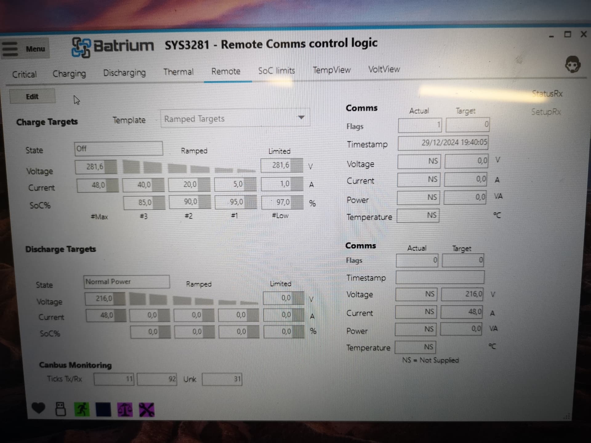
I can see this in the remote tab when the limit is reached (see the picture). The target charge voltage of 0V is really transmitted and inverter reads it correctly. Discharge current and discharge voltage is transmitted correctly.
Does anybody else observe this? Is there a solution available for that?
Setup:
Integration setup with BYD HVS protocol (latest SW release)
I had something similar and it was due to having auxiliary card discrete outputs set to allow charging and had to change it to allow charging/limited even though these outputs were not being used on the solar charger. It used them through can-buss comms.
First if you have a expansion card installed, open the menu and click hardware there is a tab for expansion where you select your control board and a expansion card . that is where you select output relays and their function.
second is in control logic then charging tab. on the left side there is a selector just about to the top that says allow limited charging. turn it on.
Hopefully that gets you working.
Anything other than that you will need to talk to James for tech support in a message
I’ve taken a look at Kuchen’s system, and there is definitely some strange behaviour across the board. 0V is definitely not what we intend, and will be looking into it, and updating this thread