Hi All. I’m seeking some feedback and comments regarding what is an acceptable voltage drop under load, and at what point do you classify a cell as weak or faulty. What other factors may be involved and are there any suggestions for testing?
My use case is EV (boat), so the load can vary drastically. Cruising load is approx 0.15C, but high load can be as high as 1.0C for short bursts (30 seconds). I’m seeing a large variation in cell voltages under all load variations, but on removal of the load cell voltages return to mostly equal.
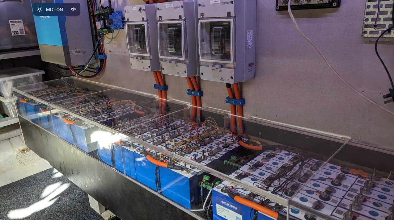
Battery pack is LiFePO4 112s. Cells are Eve LF105.
When charged to 3.33V all cells are balanced (within 0.05V).
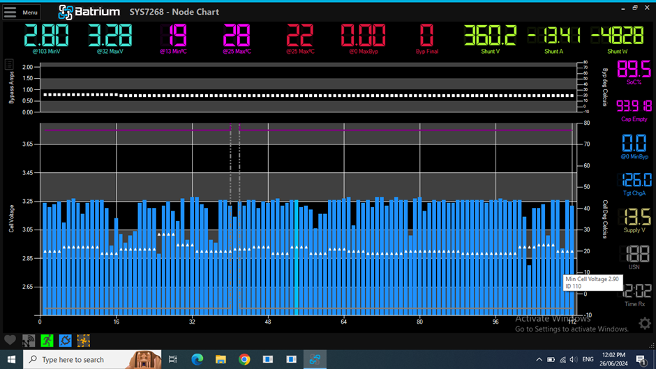
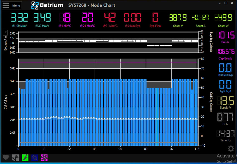
Case 1 - 13A load
“Good” cells seem to be around 3.25V, “bad” cells as low as 2.80V
What voltage drop under load is acceptable? And at what load and for how long? On return to a relatively light load (0.1C) most cells return to a normal mostly equal voltage.
All cells are connected via busbars, all connections cleaned and equal torque when installed. I’ve pointed a temperature gun at each terminal when under load and do not see any significant variation in temperature.
I have 16 new cells on hand to replace any that are deemed weak/faulty. How do I identify weak cells? Are there any tests that can be run on the cells? (Offline test with cell removed from battery pack)
Perhaps cells that appear to be weak under high load may still be usable for a light load application? (eg house batteries)
I know this is a lot of questions but I greatly appreciate community input and discussion here.
Hi Jon
you need to charge them to a higher voltage try between 3.51 > 3.52
it looks like cell 16 & 60 have very high internal resistance
i think you need to charge them up and clean all the terminals as the voltage drops with a 13a load are a worry.
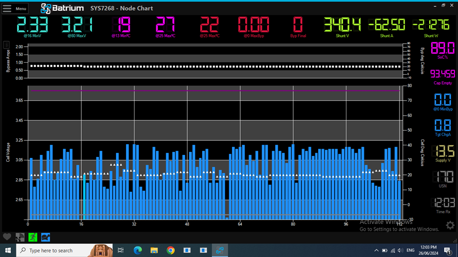
On your 62A load every cell below the 3.05v line would only have about 20% capacity remaining.
These cells are very light for there size 1.98kg for a 100ah as apposed to a Winston 100ah at 3.6kg
so you may just be pushing them a bit hard.
Se how they go after a recharge and balance , you may need to charge the really lo cells individually
Thank you for your input. I think first step will be to clean and check all the terminals as you suggest.
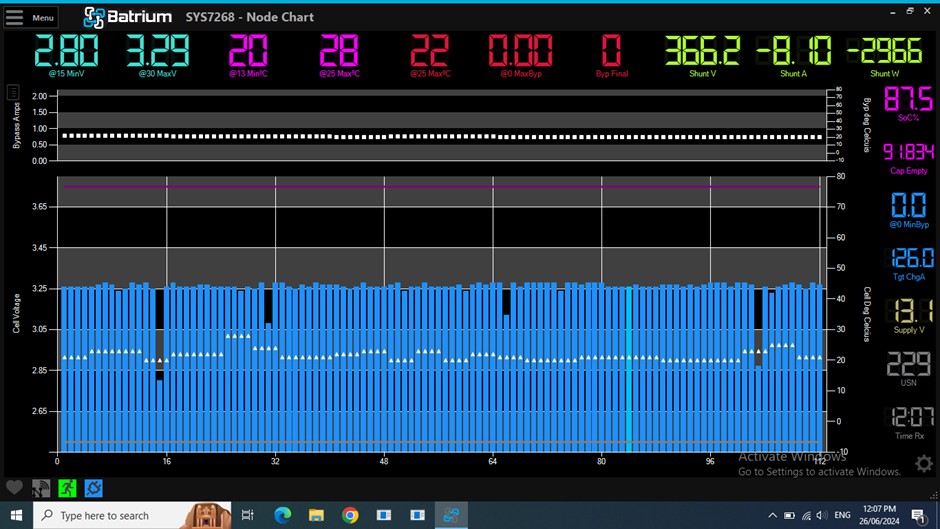
I do normally charge higher than 3.3V and the majority of the cells balance. There are 16 cells (a more recent purchase than the rest and different batch but identical make/model) that never want to charge more than 3.3V (why???), however they don’t show any of the voltage drops the others do. These are cells 81 to 96.
After the most recent full charge they looked like this:
Cells 19, 31, 109 I’ll replace. Cells 81-96 mentioned above. Cells 1-4 were briefly removed and used elsewhere as a 12V pack for a day. On return to this HV pack they no longer charge over 3.3V (why???).
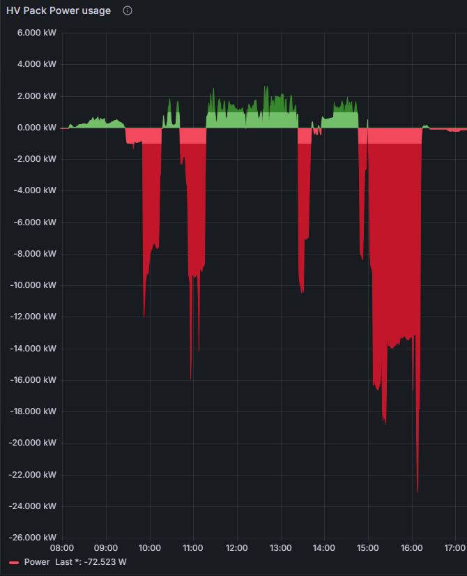
I used the system yesterday, depleting the battery from 100% down to 25%. I’m having trouble getting remote access to the BMS now to check, but reporting via Grafana indicates about 25kWh used with some recharging from solar along the way. 112 cells @ 105Ah gives a total capacity of 37kWh, so my overall capacity is down a bit but not completely off!
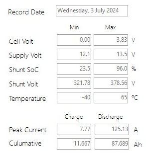
I just reestablished access to the BMS and grabbed these results from yesterday:
I think at this stage I’ll clean the terminals, replace maybe 8 of the cells showing the most variation, then run a few charge/discharge cycles and see how they behave. With a couple of sunny days they should be fully charged again by the weekend.
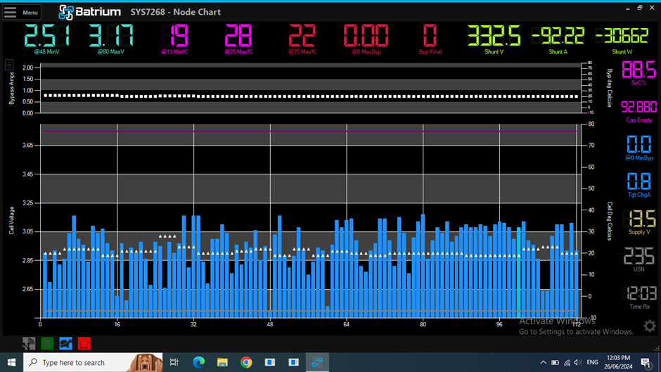
You will probably need to remove all the cells that are currently low on your latest graph and charge them separately.
the low cells are only being charged at your bypass current for the time that the other cells re in bypass
New cells are usually delivered at ~50% SOC so would take forever to charge up to 100%
just relying on the time/current that the other cells are in bypass
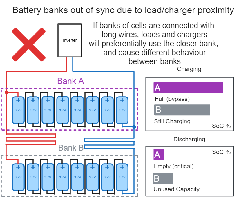
Just one more thing that comes to mind, what about length of cabling to the inverter? Are the banks length matched so that it doesn’t favour one over the others?
I am using chemtools carbon conductive grease, no problems after 9 years on this pack.
They also have a zinc grease compound.
witch is best will just depend on your mix of metals between battery terminals & lugs
Not sure I understand this James. The cells are connected in one long series - 112 cells for 360V nominal. The “banks” are simply groups of 16 cells for physical mounting reasons and to match up with a cellmate.
Ah, my bad - you’re all good there then. We find a lot of people using multi-string 48V systems and these give the issues I mentioned, but it sounds like you’ve avoided all that with a single HV string
Some cells were “weak” and have been replaced with new ones. The cells I removed seem to be holding a charge ok so I may repurpose them for lower current duties elsewhere in a 12V pack.
Top balance - it took 2-3 weeks of balancing but I finally managed to get all cells to 3.50V and they now appear to be staying balanced or balancing easily/quickly (an hour or so). I had to help the initial balance by adding some extra charge to some cells, and manually burning off charge from other cells using an automotive light globe.
Poor connections - the original cells were provided with 4mm scr ew holes which are way undersized for the application and cannot support the torque required to simply hold the busbar in place. Most of these I have drilled/tapped to 5mm and inserted grub screws as terminal posts. A small number have even been tapped to 6mm. I also found a lot of the terminal connections about 1/8 of a turn off full torque. They’ve now been cleaned and torqued properly. Note that all terminals use a washer/spring washer combination or a serrated nut so they shouldn’t be working loose. I’ve also liberally coated each connection with vaseline - found this to be much cleaner and just as effective as the no-ox grease.
Under load now I’m seeing a much more even voltage drop across all cells. A few cells did show a larger voltage drop which I resolved by a clean/torque of the terminals or swapping out the cell.
A steady load for this application can be 20-30A (0.2 - 0.3 C) and I have run them at 100A (1.0C) for a few minutes without any problems. Yes they show a large voltage drop at that load, but they recover well to a more normal voltage when the load is reduced or removed.
I do wish I had 280A cells instead of 105A, both for runtime and to support a larger load, but with over one hundred of them the cost difference becomes significant. Interestingly the cost of 280A cells is almost down to what I paid for 105A cells 12 months ago…
Thank you to everyone that got involved and helped out; after all the dramas it is still a fun learning experience.